Successful case: DEM analysis in a mobile sizing rig
Mobile Crushers
The mobile sizing rig concept is not new to mining professionals. However, its use has only become more widespread in recent years, due to advances in related areas of engineering. When compared to stationary systems that rely on off-highway truck transport, mobile sizings have significant advantages, the main ones being [1]:
- Cost savings
- Reduction of manpower required for the operation
- Decreased fuel consumption
- Decreased CO2 emission levels
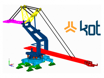
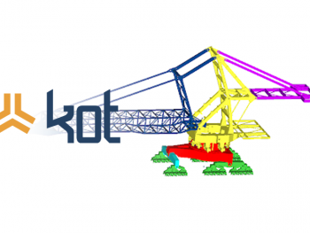
Aiming for competitive ore production, combined with the most sustainable, modern solutions and without using off-road trucks to transport materials, one of KOT’s clients wished to repower both the nominal and design capacities of one of its mobile sizing rigs, from 9,500 to 10,500 and 11,500 to 12,600 tons per hour respectively. This system can be seen in Figure 1.

Changing production capacities, nominal and design, the variation of mass flow rate and operational speed of the conveyors in the equipment directly impact the materials behavior in the receiving and unloading chutes of the mine machines.
KOT has been responsible for several studies on this mobile sizing rig. This article aims to discuss the verification of the receiving feeder and an intermediary ore transfer chute of the unit through discrete element method (DEM) simulations.
Three-dimensional modeling
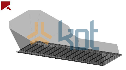
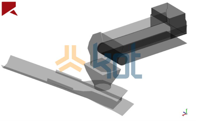
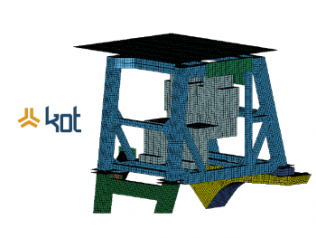
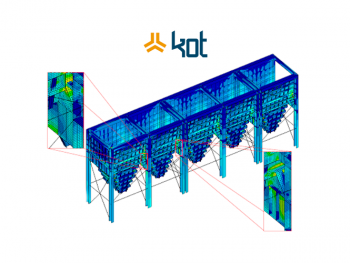
The first stage of development for the discrete element analysis was the three-dimensional models elaboration of both the feeder and the intermediary material transfer chute.
Since they are material flow surfaces models, details such as inspection doors, windows and other auxiliary devices were not modeled. Such components are generally not considered in the analysis, because they do not influence the material flow in the structure in a significant way.
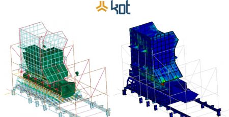
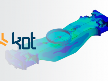
Figures 2 and 3 show some of the models developed.
Analysis
Some of the main discrete element method analyses performed for the mobile sizing rig are shown below.
- Material
KOT received characterization tests of the transported material and performed the calibration of the material model based on its characteristics.
The characterization aims to determine material properties that are input parameters for the simulations in the specific DEM analysis software (particle-particle and particle-wall interaction properties of the chute). The tests also help to understand the ore’s stream flow.
- Feeder
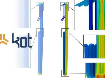
Figure 4 shows the overview and centerplane of the DEM model generated for the feeder.
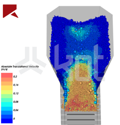
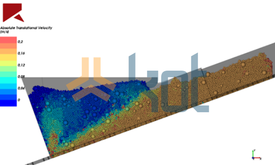
The DEM analysis of the feeder indicated the operational speeds of the equipment for some of the various material conditions that are processed by it, and an appropriate type of operation was indicated for each variation of material handled.
With this, the values obtained are compatible with the proposed repowering of the mobile sizing rig and serve as a reference for the equipment’s operation.
- Intermediary Chute
Figure 5 shows the clogging analysis of the mobile sizing rig’s intermediary chute.
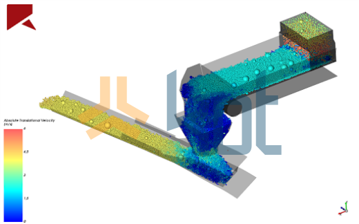
The simulations with the repowered design showed that the chute did not support the increased capacity of the conveyors for the operational conditions, since problems related to clogging were identified. Therefore, it was indicated to redesign the component.
Regarding the loads on the impact table, it was verified that the rollers in this region are able to operate under the new capacity. In addition, the analysis indicated that the plate identified as a deflector does not receive impacts from the material flow.
Simulations X Real Conditions
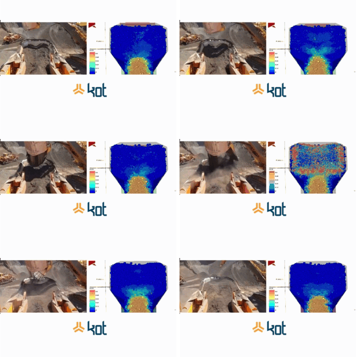
The capillarization of computational techniques has provided both the refinement of methodologies for their execution and the acceptance of the results obtained. However, even today, simulated results that visually portray real operating conditions are highly regarded by engineers and managers.
Thus, Video 1 shows a comparison between video footage of the mobile sizing rig’s feeder operation in question and the result of its DEM analysis.
Conclusion
Computer simulations can be both complemented with information collected in the field during operation, and endorsed by real conditions that exhibit great similarities.
In general, KOT can help with computational analysis and field surveys. The company can act in various sectors of the industry, from cellulose to mining, bringing appropriate solutions for your needs. Consult the team of specialists to learn more!

KOT Engenharia’s Team
With over 29 years of history and various services provided with excellence in the international market, the company promotes the integrity of its clients’ assets and collaborates in solutions to engineering challenges. For this integrity, it uses tools for calculation, inspection, instrumentation and monitoring of structures and equipment.
References:
[1] DEAN, M. et al. Selection and planning of fully mobile in-pit crusher and conveyor systems for deep open pit metalliferous applications. In: AusIMM 2015 3rd International Future Mining Conference, Sydney, NSW, Australia. 2015. p. 4-6.
[2] KOT’s collection


Leave a Reply