Successful case: structural analysis of a mining stacker.
This article will present a successful case study performed by Kot concerning the structural analysis of a stacker. Before starting the case study, some basic auxiliary concepts are shown below.
Basic concepts about structural analysis
- Stockyard machines: these are widely used, mainly in mining and port activities for bulk handling;
- Stackers: stockyard machines used for piling up bulk materials;
- Tripper: movable belt conveyor, connected to the stacker, responsible for lifting the material supplied by the conveyor from the stockyard to the stacking machine;
- Bar element: One-dimensional element type used by the finite element method (FEM). It has a geometric property of cross section and is often used to represent metal sections;
- Shell element: two-dimensional element type also used by FEM. It has thickness as geometric property and is commonly used in the representation of structures formed by metal plates;
- Plastic deformation: behavior that materials exhibit when subjected to efforts that generate internal stresses beyond their elastic limit. Plastic deformation is exemplified by permanent deformations in the material;
- Utilization index: ratio between the acting efforts (or stresses) and the structure’s resisting ones. Calculated values less than or equal to 1.0 correspond to the normative approval condition.
The stacker analyzed by Kot has a design capacity of 20,000 t/h (tons per hour) and is responsible for the formation of ore stockpiles in a stockyard.
3D Modeling
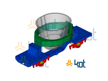
The analyzed equipment consists of a stacker and a tripper, which were modeled in finite elements to enable starting the study. For the trussed structures, bar elements were used, because they are profiled. The other machine components, as they present greater geometric complexity, such as variable section profiles, metal plates, reinforcements and local stiffeners, were represented in shell elements.
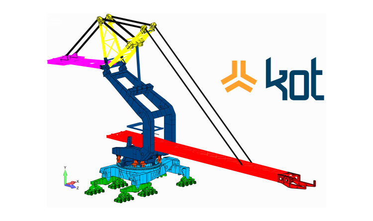
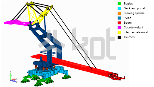
As can be seen in Figure 1.1, the stacker model includes all sub-assemblies of the equipment:
- Bogies;
- Deck and portal;
- Slewing system;
- Pylon;
- Boom;
- Counterweight;
- Intermediate mast;
- Tie-rods.
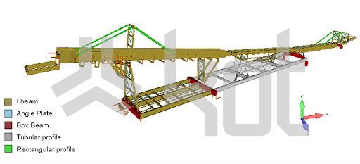
The tripper model, illustrated in Figure 1.2, shows all the metal profiles used.
The loads applied to the structures were combined as established by standard, so that different operating situations could be evaluated, covering all the normative cases. Complementary combinations, defined by Kot’s experience, were also applied.
Some of the loads applied were:
- Own weight of the structure and installed equipment;
- Material and fouling load;
- Belt tension in permanent and transient regimes;
- Overloads;
- Impact against the material pile.
Structural Analysis
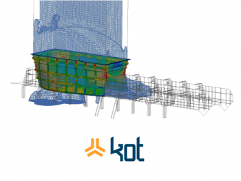
The static analysis was the first one performed. In this analysis, the profiled structures did not present any nonconformity. On the other hand, in the shell-modeled structures, utilization rates above the admissible were found in the region of the boom, under normal operating conditions, as shown in Figure 1.3.
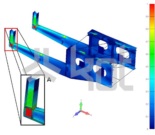
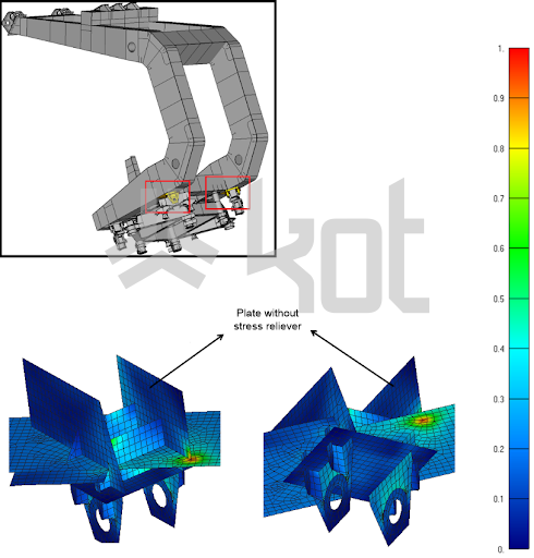
In the region of the mast connection with the slewing bogies, a nonconformity was found in the reinforcement of the mast beam, which has no complementary plate to soften the acting stresses in the region. Thus, the existing element concentrates all the effort received, generating a stress peak. This disapproval is shown in Figure 1.4.
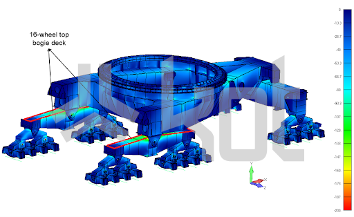
The direct comparison between acting and resistant stresses alone is not always enough to establish the strength of a structure, within a structural analysis. Instability phenomena in this type of equipment are very common – either due to operation movements, operation overloads, wind loads, among other normative factors considered – and tend to occur in stress intervals usually smaller than the elastic limits of the materials used. In order to verify these limit states, a local buckling analysis was performed with emphasis on the regions where the highest compression loads were found, being more susceptible to buckling. In the lower part of the model, for example, these regions are located in the upper deck of the equalizer beams, as indicated in Figure 1.6.
Once the verification of the structures’ static resistance is finished, the evaluation of the equipment’s service life through fatigue analysis begins. Within the structural analysis, this evaluation consists of establishing the operational resistance, i.e., the capacity that the structures have to support the nominal efforts throughout their working life, and is usually performed according to cyclical regimes of equipment operation.
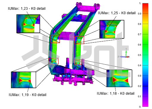
For the stacker, a 35-year operation time was considered in the fatigue analysis. In the mast were found utilization indexes above the admissible in regions that, in the static analysis, tended to suffer plastic deformation, presenting stress concentrations. Thus, the points indicated in Figure 1.5 present potential for nucleation and propagation of cracks.
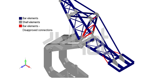
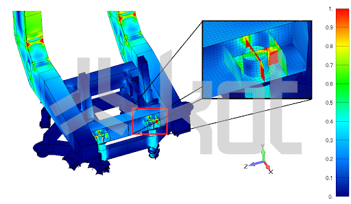
The different types of connections between the structures were also analyzed, including rigid and flexible, welded and bolted connections. In this evaluation, the beam connections shown in Figure 1.7 were disapproved for the combination regarding shock loading against the ore pile. Although the standard under which the verification was based does not include this type of loading for stackers, Kot Engenharia included it in the structural analysis because it is a possible situation that, if it occurred, would be critical for the structure.
The flexibility check, responsible for the calculations and evaluations of the structure’s displacements, was also performed. The conclusion of this stage resulted in warnings for the platforms and flanges (main longitudinal profiles) of the boom. Despite not affecting the operation of the equipment, it is important to monitor the regions, since displacements above the admissible may be responsible for damage to non-structural elements and discomfort to users.
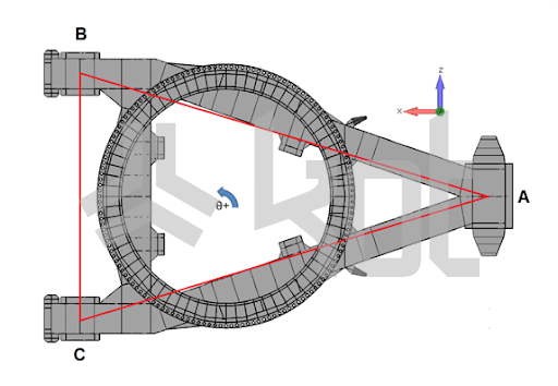
Another important check in stockyard machines is global stability. Since the stacker’s undercarriage has three points of articulation, the stability polygon of the equipment will be a triangle, as shown in Figure 1.8. Therefore, each edge of the triangle represents an axis of possible overturning. It was verified that all the minimum stability coefficients have values in accordance with the admissible ones and the stacker was considered approved in this aspect.
Finally, the machine’s jacking points were checked for structural strength, as required by international standards. The jacking can be performed at different spots, for maintenance of each of the bogies, rocker arms or equalizer beams. The reinforcement plate, in the region that serves as the jacking point for slewing bogies maintenance, presented utilization indexes above the admissible, as can be seen in Figure 1.9.
Conclusion
The structural analysis of the stacker, in some situations, resulted in non-conformities. Therefore, Kot indicated monitoring actions and reinforcements. It is important to highlight that different regions presented stress concentrations, which generated high utilization indexes both in static and fatigue analysis. This is common when the design does not consider discontinuities that may contribute to this effect, such as [2]:
- Sudden changes in thickness or cross-section geometry
- Notches, holes and keyways
- Error in the conception of the equipment’s basic design
- Failures generated during the manufacturing process.
With this in mind, it is essential that projects are evaluated by structural specialists. If your company has a need for machinery and equipment checks, contact Kot’s team for more information.
KOT Engenharia’s Team
With over 29 years of history and various services provided with excellence in the international market, the company promotes the integrity of its clients’ assets and collaborates in solutions to engineering challenges. For this integrity, it uses tools for calculation, inspection, instrumentation and monitoring of structures and equipment.
References:
[1] KOT Collection.
[2] BUDYNAS, R. G.; NISBETT, J. K. Elementos de máquinas de Shigley: projeto de engenharia mecânica. AMGH Editora, 2011.


Leave a Reply