
Successful Case: Analysis of a railway bogie
Introduction
Today Brazil has more than 30 thousand kilometers of railways in its territory [1]. These railroads are responsible for the transportation of people and materials along its extensions. From the engineering point of view, railways and wagon compositions can be the subject of studies by several disciplines. A company wished to study one of its railway bogies and asked KOT Engenharia to do the study.
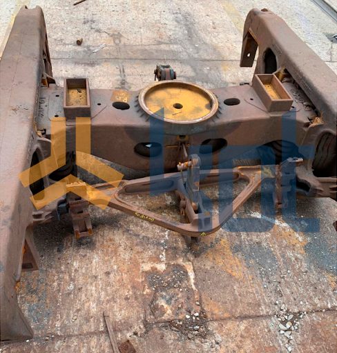
The model of bogie in question is called “Three-Piece” and is composed of two side frames and a central bolster. The main functions of this bogie are to enter the vehicle in curves and to distribute the vertical loads coming from the wagon to the wheels. Figure 1 is a photograph of the analyzed bogie.
Due to cyclic loading on the bolster, it is common for cracks to appear in the internal ribs and in the centre pivot. The scope of the service performed by KOT aimed to perform simulations to define scraping criteria for bogie bolsters, as well as to suggest structural changes focused on increasing the component’s useful life and reducing the risk of breakage. Read this article and understand more about the company’s work!
Development
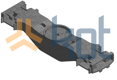
The beginning of the activities was given by the as-built of the bolster. From the information collected, it was possible to perform the three-dimensional modeling of the geometry of the object. The 3D model was adjusted to remove unnecessary details to the analysis and a mesh was generated for finite element analysis, using a specific software. Figure 2 illustrates this step of the process.
Prior to the KOT study, the company performed the instrumentation of strain gauges on the bolster and the side frame of the bogie. The data acquisition was done over five trips along the railway’s route. From the data obtained in the extensometry, it was possible to obtain the deformations with the vertical loads acting on the centre pivot of the bolster.
One of KOT’s professionals visited the company’s workshop to better understand the occurrences of cracks in the bolsters, to understand the process of recovering them, and to register failures in bolsters that would be repaired or were being discarded.
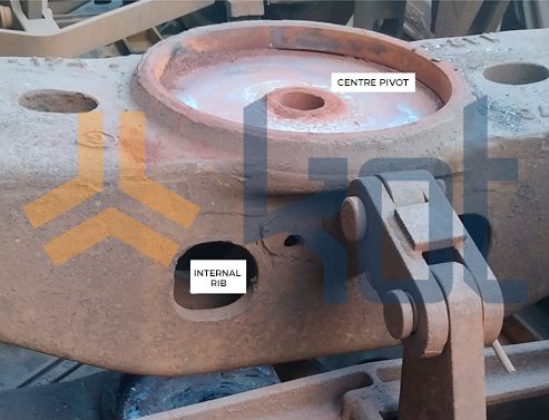
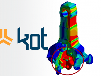
According to information gathered during the visit, the main points where cracks appear are the internal ribs and the centre pivot, illustrated in Figure 3.
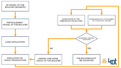
The computational simulation plan adopted in the crack propagation analysis is presented in a flowchart containing some of the steps followed in Figure 4.
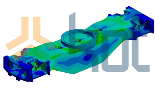
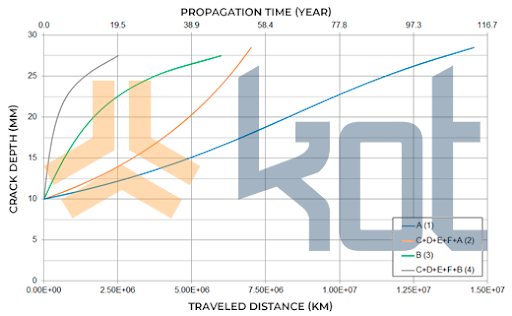
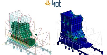
Once the analysis assumptions were defined, such as loading conditions, crack types and propagation scenarios to be evaluated, and the boundary conditions of the computational model, the simulations were performed. Figure 5 represents one of the results obtained during the static analysis of the bolster. Figure 6 illustrates the results obtained in some of the simulation scenarios of crack propagation.
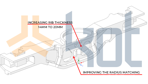
After completing all simulations and analyzing the results, it was verified that it was impossible to make geometric modifications to the current bolsters due to the restricted access to the inner part of the bolsters where the internal ribs are located. Thus, the proposed modifications were related to the design of new bolsters to be bought by the company. One of the suggested changes in the geometry of the object can be seen in Figure 7.
The simulations were rerun considering the proposed change points and one of the results is illustrated in Figure 8.

Conclusion
Linear Elastic Fracture Mechanics (LEFM) is a fatigue life assessment methodology that assumes that every component inevitably has imperfections and defects, either due to the manufacturing process or to the service condition employed. This represents an advance over traditional fatigue analysis methods, which do not consider the effects of the presence of cracks in the material. These analyses are complex and challenging, but upon completing a study, it is possible to obtain satisfactory results that lead to unique solutions for each case of analysis.
KOT has qualified employees to assess various demands and seek together with the customer the best solution to their problem. Contact us for more information!
Get in touch with KOT’s specialists team!
KOT Engenharia’s Team
With over 29 years of history and various services provided with excellence in the international market, the company promotes the integrity of its clients’ assets and collaborates in solutions to engineering challenges. For this integrity, it uses tools for calculation, inspection, instrumentation and monitoring of structures and equipment.
References:
[1] Transporte Ferroviário no Brasil, Percília Eliane, [S.]. Available at: https://brasilescola.uol.com.br/brasil/transporte-ferroviario-brasileiro.htm
[2] KOT Engenharia Collection.


Leave a Reply