
Basic Principles of Strain Gauges – Part 1
Whilst using assets during field practices we can find numerous situations, having knowledge on the tension and deformation applied onto a structure is an important tool for the identification of potential inconveniences [1]. Furthermore, it is essential to avoid that high deformation levels compromise the final outcome for which the structure or equipment was designed.
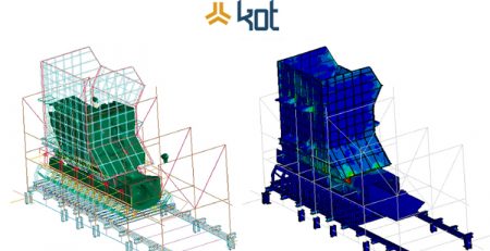
Often, mathematical models, like the ones used on Finite Elements Methods (FEM), are needed to prevent the tension behavior on a structure. There are, however, some situations which do not acknowledge the loads being applied on the object being analyzed, thus compromising the model, the accuracy of the portrayal, the results and the definition of the required actions. In these cases, to avoid these kinds of mistakes, the experimentation can be an interesting path to be followed.
In fact, several methods can be used, such as optical fiber sensors, piezoelectric, photoelastic and digital image correlation. At this initial stage of the article, we will highlight the use of strain gauges as a kind of experimentation.
What is an strain gauges?
Before introducing the concept, a rather peculiar curiosity is that the strain gauges was invented by two people almost simultaneously. Professor Arthur Ruge, from the Massachusetts Institute of Technology (MIT), was one of the inventors and the other was Edward Simmons, from the California Institute of Technology (Caltech). In 1936, whilst Simmons was investigating the tensile-deformation behavior of metals under chock loads as a student and research assistant at the institute, he made his discovery. On the opposite coast of the United States of America, Professor Ruge’s research was leading him in the same direction even though he had never met Simmons or his research [3].
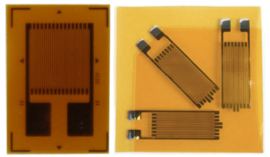
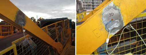
In practical terms, the strain gauge is a sensor which can be placed and glued on to the surface of the analyzed object, from which we want to understand the deformation and consequences of the tension. It can be, for instance, uniaxial or triaxial, as can be seen on Figure 1. Such methodology is very important for the inspection of those parameters, especially when the object (be it a structure, component or equipment) is in operation.
Therefore, the extensometry refers to the use of strain gauges to measure the deformation between two points in a solid body, which occurs when one of them is exposed to a force. This sensor obeys the mechanical deformation of the solid which is being instrumented according to the applied force/load. Overall, these means of measuring deformation experiment a change of electric parameter, often its resistance, which in turn leads to a current variation. Thus, said variation (measured in milliamps) is collected and its values measured, being interpreted by the data acquisition plate and available computational tools. This interpretation allows for the acknowledgement of the deformation values of the analyzed object, leading to Hooke’s law applications, enabling the deformation values to be transformed into mechanical tension and to be comparatively evaluated with the structural analyzes being promoted [2].
Hooke’s law
Based on Robed Hooke’s work, “The power of any springy body is in the same proportion with the extension”, the tension evaluations relate to the applied strains through the tension applied in a specific material, with the respective resulting deformity. The law is named after the British physicist from the 17th century who aimed at demonstrating the relationship between the forces applied on to a spring and its elasticity.
Extending the springs exploration by Hooke, it becomes clear that the majority of materials behave as the spring, with forces directly proportional to the displacement. However, in comparison with the springs, other materials have an area to be considered. The main idea is that, for instance, if a steel cylinder is pulled, the force applied onto the object is directly proportional to the deformation observed on the elastic region. Thus, there is a constant relationship between the deformation and the force applied on the object, which in turn means that the force required to neutralize the traction force is generated within the internal structure of the material.
The definition of magnitude/applied force value on to the object by a unit of area can be called tension. In other words, tension can be extended like a vector, having a value and direction presented using MPa (megapascal) or any other value unit of force over the unit of area. All-in-all, the commonly used materials in engineering have the property of stretching when pulled and of shrinking when compressed.
Figure 2 presents the relationship between the tension/deformation over a certain metal test body which is being pulled. Until it reaches point σE the tension is directly proportional to its deformation, where you can see a straight slope on the practically linear graph. This region is known as the elastic region, where Hooke’s law is applicable.
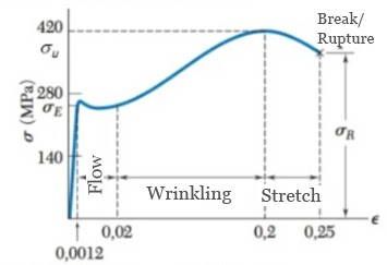
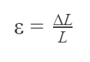
Whilst verifying the proportion principle observed in the elastic region in the graph, and considering that the whole material is stretched within said region, a relationship is obtained between the initial and final length, reaching Equations 1 and 2:
Where:
∆L = variations on length [m or other measurement unit].
L= length of the object [m or other measurement unit].
ε = Strain – specific deformation [adimensional].
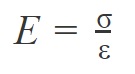
σ = Stress – stress value that is measured by the average force per unit area [Mpa or other unit of force over area].
E = longitudinal elastic modulus (Young’s modulus) [GPa or other force unit over area], which is a specific proportional constant for each material.
When should we use strain gauges?
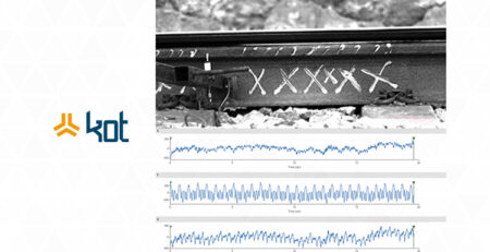
Strain gauges are used in the solution of non-conformities in structural assets, components and equipment. It is important for the promotion of structural integrity and its installation in a yard machine can be seen on Figure 3. Overall, several disciplines within engineering (Aeronautics, Civil, Mechanical, Geotechnical, among others) often use deformation measures to detect flaws in structure and assets, where these unconformities can culminate in massive human and financial impacts.
There are several ways to promote the asset’s structural integrity, as can be seen here. This non-destructive test can also be performed preliminarily and in conjunction with strain gauges, for example, to identify non-conformities and subsequently perform an instrumentation plan.
One commonplace application happens in the structural evaluation of rail and road vehicles. The instrumentation can be performed in cars, trucks, trailers, wagons, rails, couplings or other structures from which it is desired to obtain the deformation during the operation of the asset. Initially, the installation points of the sensors are determined, for later execution of the plan.
It is essential to attain the knowledge regarding the whole theory behind strain gauges and the assets instrumentation methods in order to achieve an accurate structural evaluation. More often than not, the usage of strain gauges is possible, however, it will not provide the targeted results. In other situations, it is recommended that FEM be used alongside this method.
To learn more about the applications and which are the needs for your company’s assets, make sure you continue following our blog!
Get in touch with KOT’s specialists team!

Aender Ferreira
Mechanical Technician from CEFET-MG, Mechanical / Aeronautical Engineer from UFMG and Master in mechanical projects from the same university. Before graduation, he had experiences in the mining, maintenance, project design, experimental engineering and automotive industries. As an Engineer, he started his career in the maintenance sector performing calculus activities for fatigue in aeronautical components and structures. Subsequently, he was invited to compose the Board of Directors of KOT Engineering, working in the commercial sector of the company, helding the position for almost 15 years.
References:
[1] SILVA, Anderson Langone et al. A study of strain and deformation measurement using the Arduino microcontroller and strain gauges devices. Revista Brasileira de Ensino de Física, v. 41, n. 3, 2019.
[2] ŞTEFĂNESCU, Dan Mihai. Strain gauges and Wheatstone bridges—Basic instrumentation and new applications for electrical measurement of non-electrical quantities. In: Eighth International Multi-Conference on Systems, Signals & Devices. IEEE, 2011. p. 1-5.
[3] KEIL, Stefan.Technology and practical use of strain gages: with particular consideration of stress analysis using strain gages. John Wiley & Sons, 2017.
[4] BEER, Ferdinand P. et al. Mecânica dos materiais. Amgh, 2011.
[5] BIELEN, Paul; LOSSIE, Mieke; VANDEPITTE, Dirk. A low cost wireless multi-channel measurement system for strain gauges. In: Proceedings of ISMA. 2002. p. 663-670.


Leave a Reply