Successful Case: Non-destructive testing, extensometry, structural and load increase analysis of an overhead crane.
Introduction
In the last text posted on KOT’s Blog, it was evidenced by the work done to evaluate the viability of extending the runway of an overhead crane. In addition, some basic concepts about the asset were also presented, click here, and check it out!
The present article will address a study performed by the company’s team in the analysis of an overhead crane. During the study, visual inspection, non-destructive testing, extensometry, structural and load increase analysis of an overhead crane.
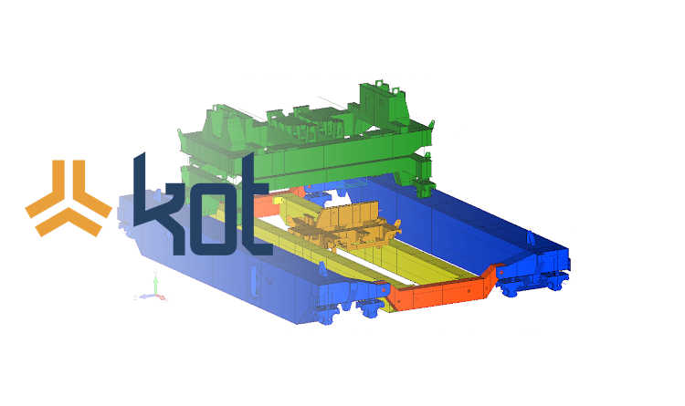
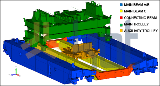
The overhead crane in question consists of two outer main beams, two inner main beams, two interconnecting beams, a main hoisting trolley, an auxiliary lifting trolley, and the travelling system. The asset’s main function is the transportation and tilting of ladles with pig iron for the steel production process. Figure 1 shows the overview of the bridge crane.
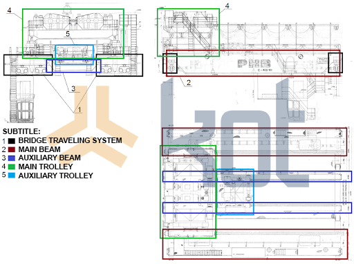
Figure 2 shows the views of the asset’s technical drawing with the indication of the systems that compose the machine.
Field Services
The services performed in the field aimed to perform the structural integrity inspection of the overhead crane, identifying points of non-conformity to indicate possible measures needed to adapt the equipment to safe operation. For this, the conditions of the structures were checked by visual inspection methods, non-destructive testing by ultrasound and penetrating liquid.
- Visual Inspection
Visual inspection was performed to check the general condition of the equipment, looking for corrosion points in the structure. It was also done the inspection of the main welded joints and evaluation of possible deformed sections and plates and design modifications.
During this inspection some points of non-conformity were found and some of them can be seen below.
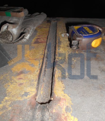
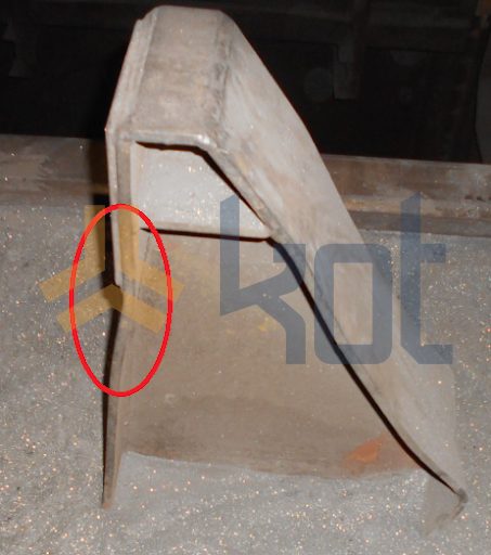
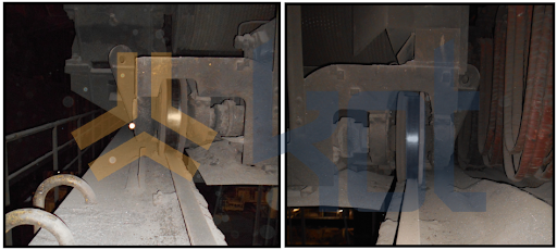
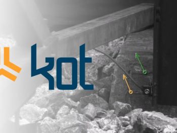
Figure 3 shows a weld at the auxiliary beam where the weld bead was not fully filled in, while Figure 4 identifies a deformation at the main trolley end stop.
Elements within the expected conformities were also found and recorded during the visual inspection. Figure 5 shows the wheel of the auxiliary trolley.
After the end of the visual inspections, KOT indicated that the best action to be taken, for the cases of the observed deviations, would be to wait for the technical report of structural analysis to verify the elements. For the elements found within the expected parameters a periodic inspection plan was indicated.
- Extensometry
The extensometry analysis was performed in several steps of commanded operation in which it was possible to evaluate the deformation at specific points of the structure. During the test, several overhead crane movements were performed in order to calibrate the computational model with a standard load with known mass.
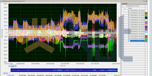
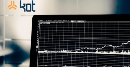
Figure 6 shows the chart containing the results obtained during the extensometry. The information will be used in the structural finite elements analysis of the overhead crane, for calibration of the computational model.
- Non-destructive testing
The non-destructive tests of liquid penetrant and ultrasound were performed on the existing welds. No non-conformities were found.
Structural Analysis
Given the non-conformities found, KOT conducted a structural analysis of the overhead crane in order to identify the points of attention in the structure and assess possible causes. Some of the objectives of the structural evaluation are listed below:
- Static structural analysis
- Fatigue analysis
- Buckling analysis
- Connection analysis.
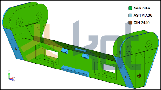
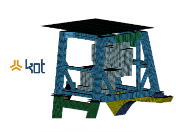
For the structural analysis of the crane, finite element models of the structure were prepared in a specific software. The finite element models developed for the analysis of the equipment can be seen in Figure 7 and Figure 8.
.
The results found during the structural simulations can be seen summarized below:
● Static structural analysis:
Points were found where the utilization index is higher than the index admitted by standard.
● Fatigue analysis:
Points were found where the utilization index is higher than the index admitted by standard.
● Buckling analysis:
No non-conformity points found.
● Connection analysis:
Points were found where the utilization index is higher than the index admitted by standard.
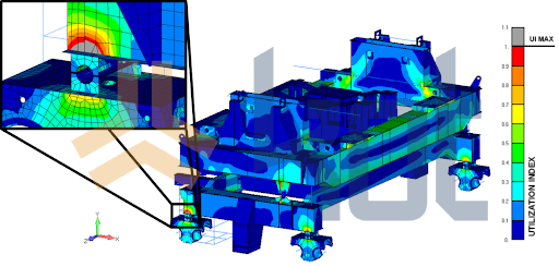
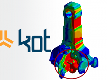
Figure 9 shows one of the results found during the static analysis of the equipment.
.
The validation of the finite element model developed by KOT was done by comparing the deformations measured during extensometry on the overhead crane and the deformations found in the model for similar loading conditions, the results of this comparison can be seen in Figure 10.
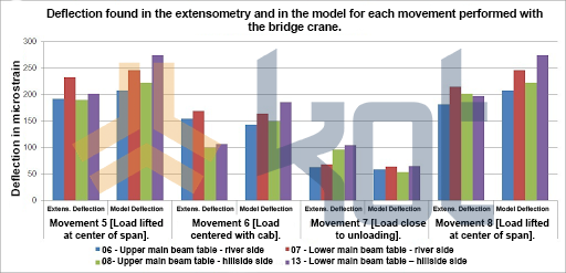
Comparing the data, it was observed that the deflections presented in the overhead crane structure are consistent with the deflections found in the model and are sufficient to guarantee that the results obtained in the model are valid for the real bridge structure. Therefore, the computational model of the crane was considered valid.
Load Increase Analysis
This part of the study was responsible for verifying the viability of increasing the bridge’s main lifting capacity to increase its capacity. For this, it was necessary to perform a structural and mechanical evaluation of the asset, considering the new loads desired by the client company.
After performing the analyses, KOT found no restrictions for the overhead crane load increase, as long as the indicated stiffeners were mandatorily installed for the new condition.
Conclusion
After the end of the analyses, due to the non-conformities verified in the structural analysis of the overhead crane, concepts of the changes or stiffeners necessary to adapt the structure to the criteria established in the standard were presented.
Fieldwork is often crucial for the development of a complete study. The identification of points of non-conformity can prevent production stoppages and even accidents. When combined with computational analysis it is possible to have a complete understanding of the working context of an asset, validating computational models and raising information that often goes unnoticed.
KOT Engenharia has employees able to work in the field, performing visual inspections, non-destructive testing, and data collection. The company’s team can also perform several computational analyses. Contact us for more information!
Get in touch with KOT’s specialists team!
KOT Engenharia’s Team
With over 29 years of history and various services provided with excellence in the international market, the company promotes the integrity of its clients’ assets and collaborates in solutions to engineering challenges. For this integrity, it uses tools for calculation, inspection, instrumentation and monitoring of structures and equipment.
References:
[1] Kot Engenharia’s archives.

Leave a Reply