Basic Principles of Strain Gauges – Part 2
The strain gauge test is an experimentation method which targets the measurement of deformations and, thus, analyzes the strain on components, structures and equipment. Such measurement can be achieved through the use of sensors fixated on the surface of the object being studied, the strain gauges.
In order to implement this methodology, it is important to know the theory behind its functioning. In the previous article Basic Principles of Extensometry – Part 1, Hooke’s law was introduced alongside its relationship with deformations in the material through the strain imposed upon it, which in turn represent the basis for research on strain gauges. In this second stage, the text will present more characteristics of the strain gauge, its functioning principles and the main types currently available.
The strain gauge’s structure
Strain gauges are sensors based on electrical resistance which behave as a resistor. It is attached to the component being studied and, when that is exposed to a deformation in a specific direction (with one, two or three axes), a potential difference is generated in the sensor.
Overall, the sensors are composed of a grid of conductive material deposited in an insulating adhesive compound. When bonded to a body that is being deformed due to a load application, the strain gauge undergoes a deformation. Thus, the meshes increase in size, generating a variation in the initial strength of the strain gauge. By applying a constant electrical voltage to the terminals of the sensor and with the variation of resistance with linear deformation, it is possible to obtain the current variation of the closed system [1].
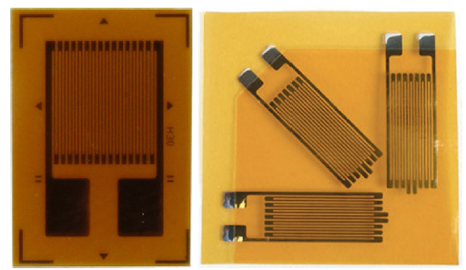
The metal grid of the strain gauges is sensitive, and the base to which it is attached adheres to the part or structure that needs to be monitored. The sensitive wire has, in most commercial strain gauges, an approximate diameter of 0.1 mm and is made of special metal alloys. The grid is embedded inside a thin plastic film or between 2 sheets of paper. Examples of uniaxial and triaxial strain gauges are shown in Figure 1.
The principle of the electrical conductance
The functioning of the strain gauges is basically based on the principle of electrical conductance and depends mainly on the geometry of the analyzed structure. It is designed mostly based on the phenomenon that the specific length of a given resistance wire is directly proportional to the resistance of the wire, as can be seen on Equation 1 [3].
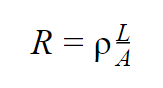
In which:
R = wire’s resistance;
ρ = resistivity;
A = area of the cross-sectional area of the specific wire.
Assuming that when the wire is pulled, the area of its cross-section is reduced, using Equation 1, Equation 2 is obtained.
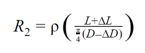
Where:
R2 = new resistance generated due to the change in dimensions and is also called deformed resistance;
D= diameter of the object;
∆D = variation on the diameter of the object.
Grounded on the strain equation and replacing ∆L by the variation in the strain gauge resistance due to the stress and L by the resistance factor inherent to the strain gauge, it was obtained Equation 3:
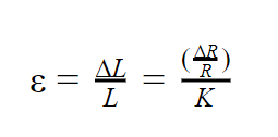
In which:
∆R = variation in the resistance of the strain gauge due to the deformation;
R = resistance of the strain gauge;
K = strain gauge measurement factor.
Wheatstone bridge
In general, it is noticed that a strain gauge works according to the basic principle of a simple metal conductor wire that tends to have a variation in its length, cross-sectional area and resistance due to a certain applied voltage.
Extrapolating this concept, all configuration strain gauges are based on the concept of a Wheatstone bridge, which is a network of 4 resistors. Simply put, one or more of these resistors can become active sensor elements. In other words, a Wheatstone bridge is a voltage divider circuit, as shown in Figure 2, which can detect small changes in resistance.
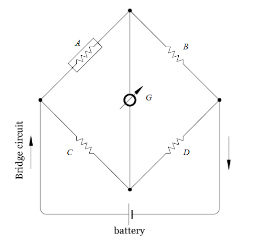
This bridge is the electrical equivalent of two parallel circuits. Thus, RA/RB and RC/RD compose these two circuits, where they represent the average output tension. The output of a Wheatstone bridge is measured at the interface.
A physical phenomenon, such as a change in the deformation applied to an object being monitored or a change in temperature, alters the resistance of the sensor elements in the Wheatstone bridge. Therefore, its configuration is used to help measure small variations in resistance. This variation in the resistance that the sensor elements produce induces a voltage variation that, in practice, corresponds to a physical change in the object being measured or monitored.
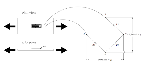
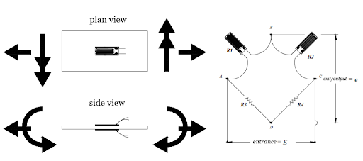
Simply put, there are three types of strain gauge configurations: ¼ of bridge, ½ bridge and full bridge. Each one of these strain gauge configurations is then divided into several subtypes. Two examples can be seen on Figures 3 and 4.
Kinds of strain gauge
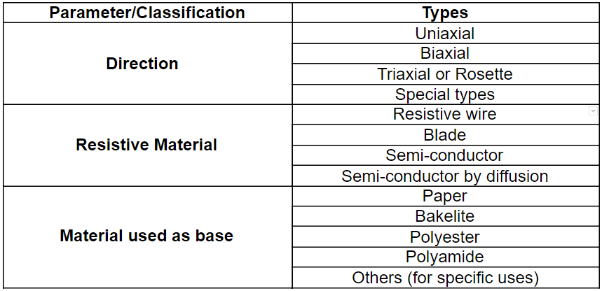
There are several kinds of strain gauge and choices must be made according to several criteria. Such criteria include the level of deformation, the temperature in which the monitoring is being carried out, the material of the object, the environment, the geometry, the manufacturer, the use, among other factors. The literature and manufacturers provide various classifications and types of strain gauges for use. In a simplified way, Table 1 presents the most common kinds of strain gauges which can be used for tests.
The possibilities of using strain gaugey for solutions in structural integrity are grand. But it is important to note that there are also limitations to the use of this tool. In some situations, its use is not the most suitable, and there are more adequate possibilities according to the need for the study. In certain cases it is recommended to use only finite elements method (FEM). In others, the junction of FEM and strain gauges. KOT has extensive experience in the field and can provide its customers with strain gauge solutions for testing and monitoring to promote asset integrity.
Get in touch with KOT’s specialists team!

Aender Ferreira
Mechanical Technician from CEFET-MG, Mechanical / Aeronautical Engineer from UFMG and Master in mechanical projects from the same university. Before graduation, he had experiences in the mining, maintenance, project design, experimental engineering and automotive industries. As an Engineer, he started his career in the maintenance sector performing calculus activities for fatigue in aeronautical components and structures. Subsequently, he was invited to compose the Board of Directors of KOT Engineering, working in the commercial sector of the company, helding the position for almost 15 years.
References
[1] SILVA, Anderson Langone et al. A study of strain and deformation measurement using the Arduino microcontroller and strain gauges devices. Revista Brasileira de Ensino de Física, v. 41, n. 3, 2019.
[2] BIELEN, Paul; LOSSIE, Mieke; VANDEPITTE, Dirk. A low cost wireless multi-channel measurement system for strain gauges. In: Proceedings of ISMA. 2002. p. 663-670.
[3] BESTECH. UNDERSTANDING THE FUNDAMENTALS OF STRAIN GAUGE. 16-09-2019 Disponível em: https://www.bestech.com.au/blogs/strain/understanding-fundamentals-strain-gauge/. Acesso em: 3 de março. 2021[4] ANDOLFATO, R. P., CAMACHO, J. S., de BRITO, G. A., Extensometria básica, (NEPAE UNESP, Ilha Solteira, 2004)
[4] ANDOLFATO, R. P., CAMACHO, J. S., de BRITO, G. A., Extensometria básica, (NEPAE UNESP, Ilha Solteira, 2004)


Leave a Reply