What is concrete and what are its tests? – Part 1
Concrete is the name given to the material resulting from the appropriate mixture, known as mix ratio, of cement, water, coarse aggregate (gravel) and fine aggregate (sand). The composition of this material with steel bars generates the reinforced concrete.
When in its plastic or fresh state, concrete can be molded in desired shapes and dimensions. On the other hand, when hardened at the end of cimentitious material hydration process, a process usually called curing, it has high compressive strength, around 20 MPa to 90 MPa.
Due to its advantages, reinforced concrete is currently the world’s most widely used structural material.
BUILDING PATHOLOGIES
Over the useful life of the construction, deviations in design, construction, use and maintenance, in addition to the natural aging process of the material, result in the deterioration and consequent manifestation of defects, such as:
- Cracks
- Reinforcement corrosion
- Loss of performance, that is, the loss of expected characteristics and functionalities of the structure, or material, during its useful life.
Understanding anomalies manifestation and cause mechanisms therefore becomes essential for a structure’s safe operation and maintenance.In this regard, the holistic approach of understanding the material, the design, the construction, the use, and the necessary maintenance and recovery processes of structures is commonly referred to as ” Building Pathology”.
CONCRETE STRUCTURE TESTS
Also during the concrete structures construction, quality control tests of the material are performed, such as the ‘Slump Test’ and the rupture test of specimens sampled from the batches of concrete used.
These tests are used to evaluate the concrete’s conformity to design and construction parameters.
Although useful, these tests are representative of a limited period of the concrete structure’s useful life and have some obstacles, such as:
- Unavailable design documentation for evaluation;
- Structure anomalies manifestation after a long period in service;
- When there are doubts about the concrete quality or specific parts geometry (e.g.: beams, columns, slabs, etc.), and/or their reinforcement;
- When it is necessary to obtain details of possible anomalies presented during the asset’s operation.
On these occasions, inspection, structural analysis and tests (destructive or not) are extremely important to obtain an adequate evaluation of the existing problem. It is noteworthy that only in possession of this diagnosis it becomes possible to define the need and the appropriate correction method.
Diagnostics optimize asset life, increase reliability levels, reduce the need for excessive corrective maintenance, among other advantages.
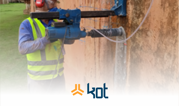
In addition to visual inspection and concrete structural project auditing, KOT also performs tests on steel and concrete structures. The objective of this text is to address some of the company’s methodologies used in concrete bodies.
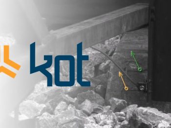
Ultrasonic test for concrete
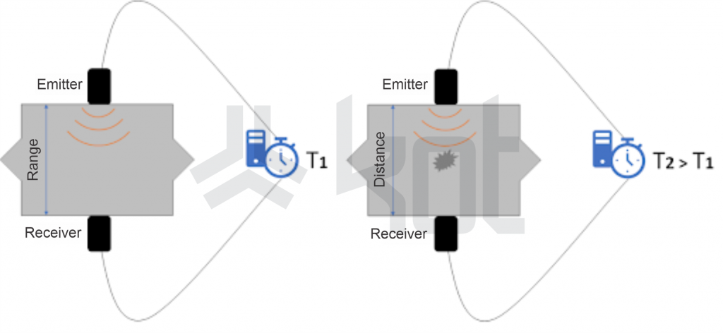
The working principle of the ultrasonic concrete test is to measure the propagation time of an ultrasonic wave through a concrete piece.
The propagation time depends on the concrete density and elasticity modulus, and changes as a function of:
- Compacting conditions during construction;
- Concrete mix ratio, curing conditions;
- Anomalies over the concrete piece.
To measure propagation speed it is necessary to have equipment composed of electroacoustic transducers (emitter and receiver) and a computer to perform the acquisition, processing and interpretation of the captured signals.
In addition, it is necessary to precisely know the propagation range for the propagation speed calculation. Figure 1 schematizes this process.
With this in mind, ultrasonic test in concrete can be applied to:
- Concrete homogeneity determination in structures;
- Define areas where more detailed investigation is recommended;
- Monitor the evolution of concrete properties over the structure’s service life;
- Determine the concrete’s elasticity modulus in service.
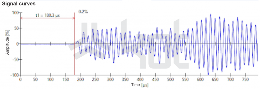
Figure 2 exemplifies an ultrasonic result for concrete.
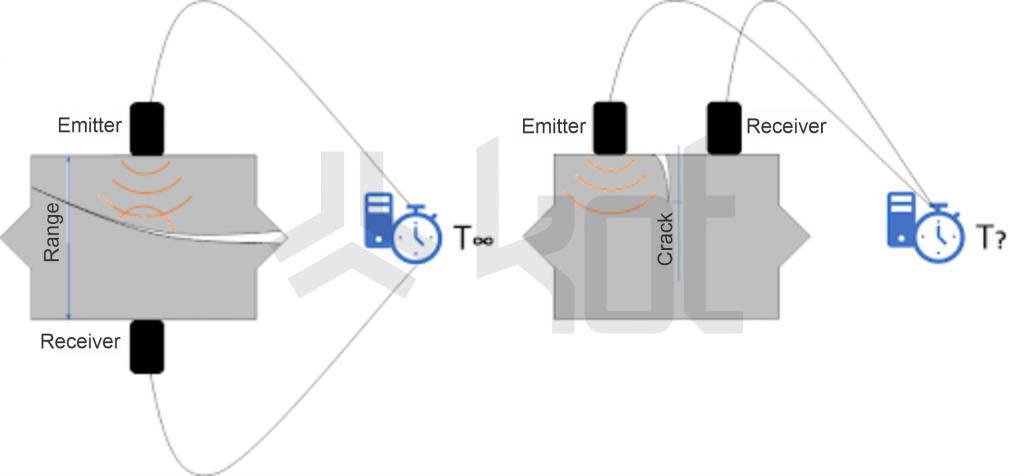
In case of piece discontinuity, ultrasonography can be useful to define its occurrence and investigate the propagation depth of cracks or voids. This process is illustrated in Figure 3.
Another useful application is using ultrasonography to estimate concrete compressive strength, a procedure that can be complemented by sclerometer and core drilling tests.
This approach is particularly interesting for the commissioning and investigation of large and/or highly responsible structures, such as:
- Bridges, overpasses and other Special Structures such as:
- Tunnels, railroads and highways;
- Buildings to support equipment (crushers, silos, mills, etc.) and other processes.
This test is standardized by Brazilian and international standards. Still, it is essential to understand the structural behavior and interpretation of the data obtained.
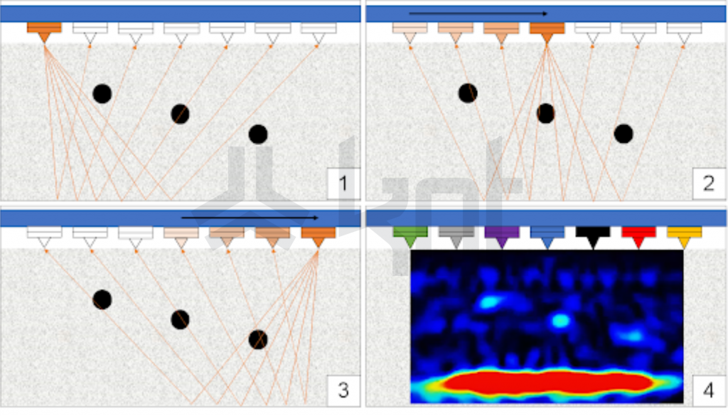
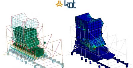
ULTRASONIC CONCRETE TOMOGRAPHY
Over the past 30 years, ultrasonic concrete tomography, or concrete tomography, has become widespread as a tool for non-destructive investigation of concrete structural parts.
According to White, the technology has historically been used to define concrete piece thickness, elasticity modulus, conformity, and anomaly detection.
It is based on the emission and reception of ultrasonic waves through a transducer array. Across the propagation path in an inhomogeneous environment (such as concrete), refractions and reflections are obtained that can have their location triangulated and also evaluated as to the level of ‘resistance’ to wave propagation.
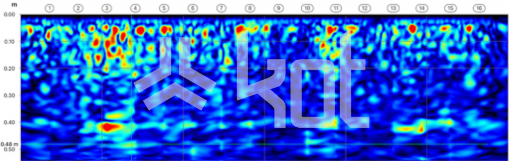
With this data, a software program is used to build two-dimensional images of the tested section. Figure 4 exemplifies this process.
In this configuration, images closer to reddish tones indicate regions of higher heterogeneity, such as
- Displacements;
- Voids;
- Reinforcement bars.
On the other hand, bluer shades indicate areas of low reflection, that is, with higher homogeneity. Figure 5 exemplifies a test result.
The most modern devices have ceramic transducers that do not require the use of a coupler and have a wide frequency range available, meaning versatility in the investigation of different geometries and concrete types.
Another great advantage of this test is the possibility of investigating structures with only one accessible face, for example:
- Investigations in concrete structural tunnel walls;
- Checking the grouting of active reinforcement sheaths in prestressed bridges;
- Defect and discontinuity investigations in concrete parts in general, such as in beams, columns and slabs;
- Measuring the thickness of concrete parts where only one side is accessible.
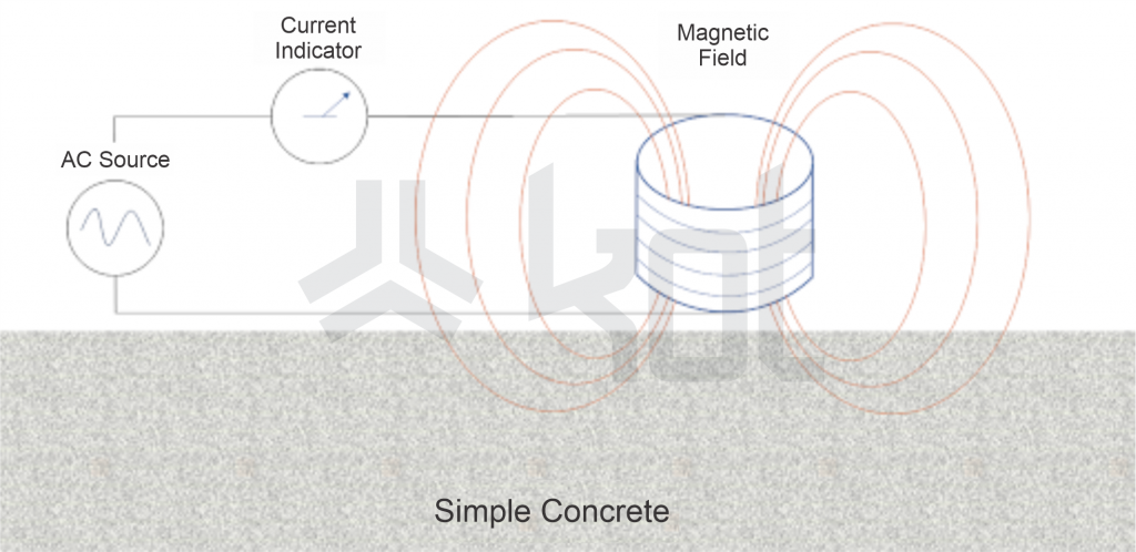
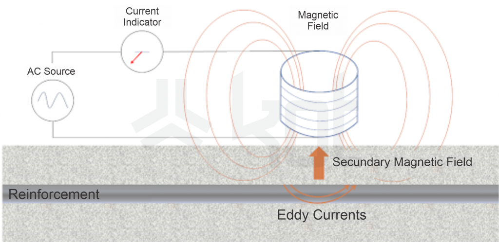
PACOMETRY
Pacometry is the test that uses electromagnetic induction to evaluate the presence, cover, and, in some cases, the diameter of reinforcement bars (rebars) in reinforced concrete pieces.
Commercial pacometers can be divided into two classes, being:
- Based on the principle of magnetic reluctance;
- Based on the measurement of eddy currents.
Eddy current based measurements are possible due to the fact that when a magnetic field is brought near a conductive material, electric currents (eddy) are aroused in this conductive material.
In turn, eddy currents change the original magnetic field configuration. In a practical way, this change is then interpreted to indicate the presence of a steel bar, as illustrated in Figure 6 and Figure 7.
KOT Engenharia has equipment with adequate productivity to perform tests on parts with large areas, such as slabs. However, the most usual is that this procedure is performed in smaller areas in order to:
- Assist in performing ultrasonic or pacometry tests;
- Control the quality regarding the positioning and cover of reinforcement bars after pieces concreting;
- Investigate structures where design documentation is not available;
- Removing testimonies from structures in service (to be commented on in a future post);
- Locating ferromagnetic materials embedded in concrete (pipes, inserts, etc.).
Limitations of this method present themselves in some situations, such as:
- When investigating areas with high bar density or with the presence of secondary electromagnetic fields;
- The diameter of the bars, when possible, can be difficult to read;
- The second layer of bars for reinforcement investigation is almost always unfeasible.
Thus, it is possible to state that performing this test requires knowledge about the method and its application.
After reading the text, it is possible to conclude that it is not enough to have modern and technological equipment to perform a correct structural evaluation. Besides the tools, it is necessary to master the concepts, from the fundamentals to those involving the reading and interpretation of the acquired data.
In this sense Kot Engenharia can truly help, owning proper equipment and specialized labor for the execution of services. Contact the company’s team.
Want to read more about concrete, its tests, and how Kot can be helpful to your business? Follow the company’s Blog and LinkedIn! The next article to be published will be Part 2, containing other testing methodologies for concrete bodies and/or structures.
KOT Engenharia’s Team
With over 29 years of history and various services provided with excellence in the international market, the company promotes the integrity of its clients’ assets and collaborates in solutions to engineering challenges. For this integrity, it uses tools for calculation, inspection, instrumentation and monitoring of structures and equipment.
References:
[1] SILVA, Ney. Concreto armado. Notas de aula – Universidade Federal de Minas gerais. Belo Horizonte, 2021.
[2] PFEIL, Walter. Concreto armado Vol. 1. Rio de Janeiro: LTC, 1985.
[3] IAEA. Guidebook on non-destructive testing of concrete strutures. Vienna: IAEA, 2002.
[4] SOUZA, RIPPER. Patologia, recuperação e reforço de estruturas de concreto. São Paulo: Pini, 1998.
[5] MACDONALD, Susan. Concrete: Building Pathology. Oxford: Blackwell Science, 2009.
[6] ASSOCIAÇÃO BRASILEIRA DE NORMAS TÉCNICAS – NBR 8802: Concreto endurecido – Determinação da velocidade de propagação da onda ultrassônica – Método de ensaio, 2019.
[7] AMERICAN CONCRETE INSTITUTE – ACI 228.2R:2013: Report on Nondestructive Test Methods for Evaluation of Concrete in Structures.
[8] WHITE, Joshua Benjamin. Ultrasonic tomography for detecting and locating defects in concrete structures. 2012. Theses – Master of Science, Texas A&M University, 2012.

Leave a Reply