Success Case: CFD analysis in movable hood
As computational power has advanced over the years, a new methodology for solving engineering problems has emerged. Better known as CFD, the Computational Fluid Dynamics is a powerful tool responsible for helping to solve countless challenges in the fluid mechanics and heat transfer disciplines. This article shows in detail the work done by KOT’s team in the study of a movable hood of a dedusting system of a converter.
Introduction
A steel industry wanted to make changes to the geometry of the movable hood of the converter’s dedusting system. Before implementing the modification, the company requested a comparative study between the asset’s constructions to act more assertively.
The equipment in study is composed of sets of pipes with internal water flow for cooling the gases coming from the converter. By using CFD, the study evaluated the cooling behavior and temperature distribution on the wall of the objects and inside the pipe circuit by the water flow.
Modeling the structure
The new proposed geometry was modeled in finite volumes using a specific software. As the proposed pipe sets are symmetrical to each other, 2 sets were prepared, as these are enough for the simulation. Besides presenting satisfactory performance, this also reduces the costs required for the computational processing of the analysis.
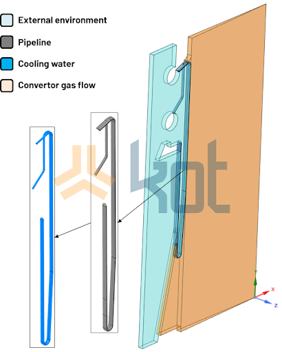
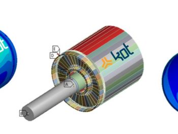
The central pipe of the set was modeled completely and one half of another pipe at each end, thus it was possible to achieve symmetry in the temperature distribution in the structure. For an easier visualization, see Figure 1, which illustrates the model of one of the groups produced.
Boundary conditions
Some of the boundary conditions considered in the analysis are shown in Figures 2 and 3.
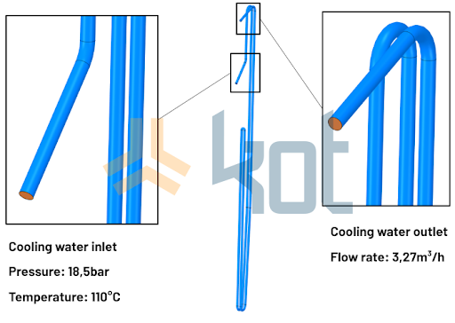
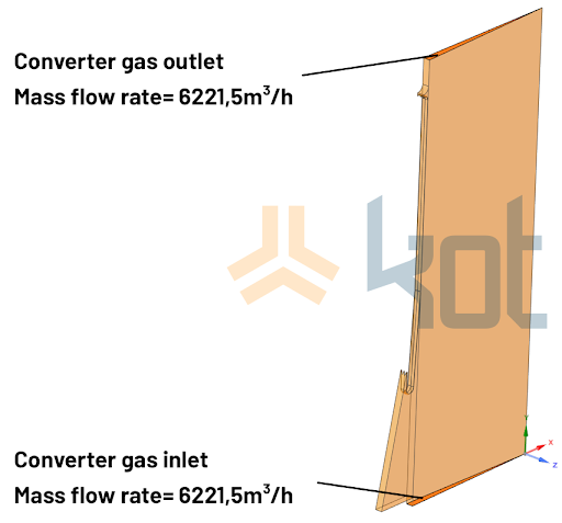
Besides those presented, other boundary conditions such as water convection, convection and radiation of the gas and ambient air, contact region of the structures, among others were also considered.
Results
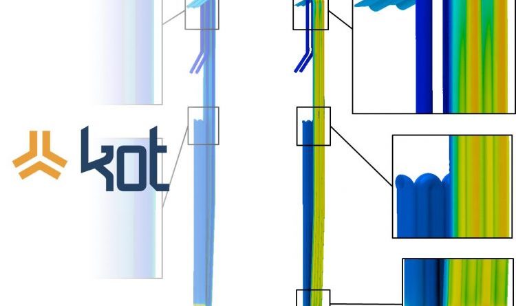
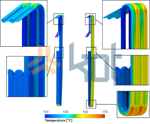
The CFD analyses performed made it possible to verify the temperature distribution along the movable hood structure, as shown in Figure 4, and in the three fluids: converter gas, cooling fluid and ambient air. In addition, the pressure distribution of the cooling fluid along the piping was obtained.
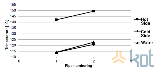
The average temperature values found in the pipes of the movable hood and in the cooling water can be seen in Figure 5.
After analyzing the results, it was found that there was a tendency for the temperatures to increase after the change in the movable hood. This fact could lead to a worsening of the operational conditions of the structure. With this in mind, it was proposed to increase the total flow rate of the cooling system and the simulations were performed again with this new condition.
The results of the initial geometry and the new proposal, with and without increased flow rate, can be found in Table 1. With this information presented, it was possible to compare the values to verify the performance of each of the geometries.
| Parameter | Initial geometry | Proposed geometry | Proposed geometry with increased flow rate |
| Heat transfer from the converter gas to the movable hood | 7849,0 kW | 7960,0 kW | 7975,8 kW |
| Higher temperature in the structure | 143,3 °C | 149,6 °C | 147,3 °C |
| Lower temperature in the structure | 112,8 °C | 114,0 °C | 111,7 °C |
| Water inlet temperature | 110,0 °C | 110,0 °C | 110,0 °C |
| Water outlet temperature | 123,5 °C | 123,6 °C | 116,9 °C |
Another important aspect of the analysis of the pipe set with the new geometry is the ability of the distributor pipe to provide similar flow rates between all sets that compose the movable hood. Remembering that the flow rate is directly proportional to the velocity, Figure 6 shows the results obtained from the velocities along the distributor pipe.
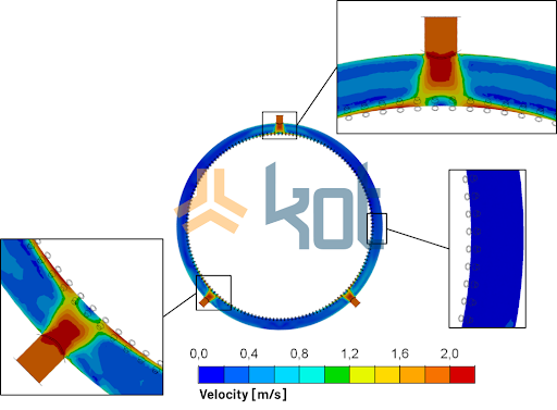
It was noted that the highest flow rates are in the regions near the cooling water inlets. This variation of the flow rate in the different sets of piping indicates that sets with different thermal gradients are found. However, this situation is mitigated because the ratio variation is small and therefore poses no risk to the structure of the movable hood.
Conclusion
To seek operational optimization and maximize the performance of the assets, it is essential that the proposed changes are validated with reliable data based on technical studies. Although changing one condition may contribute to the improvement of the system, it is necessary to have a holistic view of it, understanding the interdependence between the variables that affect the operational performance. Such condition was evidenced in the improvement of the movable hood, although the new geometry was an important factor, it was necessary to adjust the operational conditions of the system.
The mastery of computational tools should always be aligned with the engineers’ knowledge of the nature and operation of the equipment in its practical application. KOT has professionals trained to understand and evaluate the best solutions for the engineering challenges present in the day-to-day industry. Contact our team for more information.
Get in touch with KOT’s specialists team!
KOT Engenharia’s Team
With over 29 years of history and various services provided with excellence in the international market, the company promotes the integrity of its clients’ assets and collaborates in solutions to engineering challenges. For this integrity, it uses tools for calculation, inspection, instrumentation and monitoring of structures and equipment.
References:
[1] Kot Engenharia’s archives.


Leave a Reply