
Structural safety: basic concepts and interpretation of results
What is structural safety?
Structural safety is the condition in which a structure operates with expected performance. A more technical and precise definition is addressed by Leonhardt and Monning, who define that the concept refers to the structure’s ability to resist actions and stresses with an adequate safety margin [1].
The abovementioned definition developed by the authors, who are a reference in the studies of reinforced concrete structures, is interesting because it presents two of the most relevant concepts to the theme: capacity (or resistance) and actions (loads and environmental influences).
Capacity: strength, serviceability and durability
The capacity of the structure, in general, refers to its mechanical resistance, that is, the maximum effort that the structure is capable of withstanding. Furthermore, in the context of strength, serviceability must also be taken into account according to structural purpose.
For example, a slab designed to support a high-precision mechanical equipment not only needs to resist the loads imposed by this object, but the structure’s displacements also need to be compatible with the tolerances associated with the precision tolerances of the equipment in question.
The capacity to comply the intended structural performance during deterioration (aging) and to maintain a structure throughout its designed working life defines its durability. Phenomena such as the action of corrosive agents and the aggressiveness of the environment are taken into account in this analysis.
Actions: intended use, working life and stages of a structure
In short, actions consist of everything that requires a response from the structure, which are:
- Gravitational loads: the structure’s own weight and what it supports;
- Actions influenced by the environment: insolation, wind, rain, temperature variation, etc.;
- Actions resulting from the use of the structure: use overloads, accumulation of materials, dynamic loads, etc;
- Extraordinary actions (which may or may not occur): the impact caused by the collision of a vehicle on a viaduct column, for example.
Naturally, the possible structural actions depend on the intended use. A viaduct, for example, is subjected to different loads than an industrial process building.
In addition, the expected lifetime of each structure is also a factor to be considered. For example, the design working life of a bridge is directly related to the number of vehicles that will pass over it. This number is also one of the relevant parameters for its fatigue design, another important consideration in the design of a bridge and other monumental building structures.
Once the actions and resistance of an structure have been identified, these quantities are compared, as shown in Figure 1.
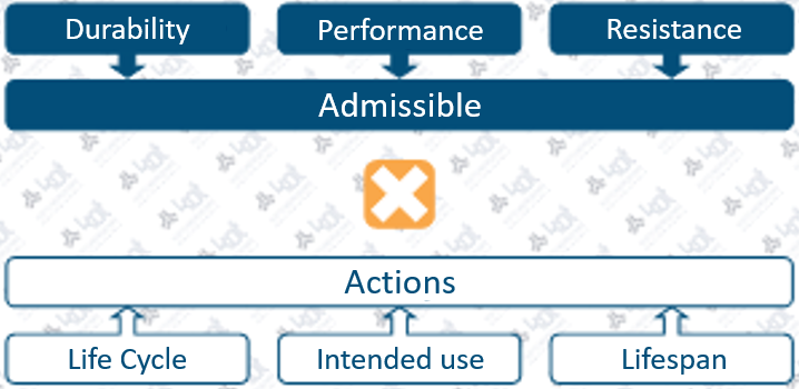
Thus, when the structural resistance surpass the defined actions, it becomes possible to state that the structure or equipment is fit for operation. Otherwise, modifications or reinforcements are necessary.
Structural safety assessment methodologies
Starting from this concept of structural safety, the next step is to clarify how the process is indeed carried out. Therefore, there are different methodologies for structural safety assessment, and this article presents the two of the most used methods in recent decades.
Allowable Stress Design (ASD)
Firstly the Allowable Stress Design (ASD). It is the oldest one and its main advantages are its simplicity and agility.
Traditionally, all predicted loads are simultaneously considered with their expected value – known as nominal value – although different considerations can be considered according to the specific scenario.
The structural analysis is then carried out and the stresses (via load effects) are obtained and compared with the admissible values, which consist of the material strength reduced by a pre-set global safety factor. The safety factor is defined by technical standards and established based on the experience of the engineers who are part of the normative committees.
Thus, it is possible to say that the main disadvantage of the ASD method is its experience-based methodology, since the associated risk is not scientifically known (meaning statistically defined). As a result, this method has fallen into disuse and is currently not adopted by the main international technical standards in the structural field.
Load and Resistance Factor Design (LRFD)
This method, known as the partial factor method has as its main advantage the application of probability theory to define the values of actions and material strength [3].
In contrast to ASD, LRFD does not use a global factor of safety. Instead, increasing loads and decreasing resistance factors are applied. Such factors are defined statistically in order to obtain an already known reliability, taking into account the following aspects [2]:
- The possibility of an action being larger than expected;
- The possibility of several actions taking place simultaneously;
- The possibility of the material’s strength being lower than expected;
- Uncertainties related to the effects of actions, the geometric properties of the structure and the specific characteristics of the material.
This probability of failure varies according to the normative set used. In Brazil, for example, the ABNT NBR 6118:2014 standard, referring to reinforced concrete structures, establishes that:
“For the purposes of this Standard, the lower characteristic strength (of concrete) is assumed to be the value that has only a 5% probability of not being achieved (…).”
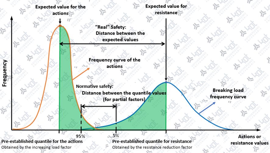
That is, even if the resistance reduction factors are applied, the material’s strength will be lower than that designed in only 5% of the scenarios, as explained in the graph shown in Figure 2. The same reasoning applies to loads: they will be increased, but a marginal chance of the design value being surpassed will still remain.
Furthermore, it is important to emphasize that the method in question is guided by limit states, which are defined according to the Brazilian standard ABNT NBR 8681:2003, as:
“States beyond which the structure will no longer fulfil the purposes of construction.”
That is, they are unwanted conditions that must be avoided in the design of the structure, which are divided into 2 (two) groups: ultimate limit states (ULS) and serviceability limit states (SLS), as illustrated in Figure 3 below.
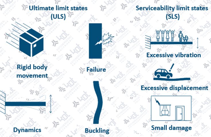
Ultimate Limit States (ULS)
Simplistically, it can be stated that Ultimate Limit States are related to structural resistance. When an ULS is detected, the structure (or part of it) must be brought to a halt. Therefore, generally each national standards define those ULS that must be checked in a structure. In Brazil, this aspect is met again by the ABNT NBR 8681:2003 standard, which presents the following mandatory evaluation ULS:
- Rigid body movement: when a structure moves as a whole. It is most common during the construction phase of the structure;
- Failure: when a structural component has lower mechanical strength than necessary;
- Dynamics: when the dynamic response leads the structure to instability;
- Buckling: when the structure becomes unstable due to its deformation, even though failure has not yet been reached.
Serviceability limit states (SLS)
Related to the performance and durability of the structure, when an SLS is detected, the structure no longer meet the specified service requirements for which it was built. Although it does not indicate an imminent failure, the occurrence of an SLS is defined as a non-compliance.
ABNT NBR 8681:2003 indicates that SLS are characterized by:
- Excessive or uncomfortable vibration: repetitive movements that make it difficult and/or impossible for an individual to remain in the structure;
- Excessive displacements: displacements that can cause the use of the structure to be impaired. For example, a deformed slab causing water to accumulate in a region;
- Minor damage: deformations that cause minor damage but that do not compromise the structure, such as cracks in the corners of windows.
Results assessment
Although introductory, the concepts discussed in this article help with the basic evaluation of results obtained in structural verifications. Thus, as in calculation memories and technical reports, when evaluating such results it becomes important to:
1 – Identify the methodology used for the structural safety assessment
It is important to be aware of which set of regulations and which methodology is being used. In most countries (as in Brazil, Europe, Australia and the United States) the current methodology is the Limit States Method. However, some industry sectors still use the allowable stress method for specific assets.
2 – Identify whether all relevant Limit States have been assessed
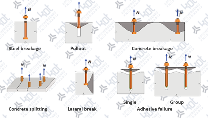
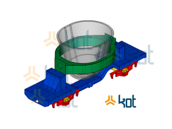
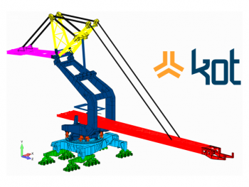
It is extremely relevant to verify if the structural components resist the construction process. Steel or reinforced concrete parts, for example, can be hoisted during construction and such operation can be a critical condition for these components, as shown in Figure 4.
In addition, the structure must also be evaluated in a maintenance condition. In bridges and viaducts, for example, the assessment of maintenance condition has great importance since such structures maintenance process may require their suspension by means of hydraulic cylinders.
Furthermore, the possible limit states also depend on the nature of the known structural actions. In a tensile-only base plate connection, for example, all associated failure modes must be evaluated [9], but there is no need to check the failure modes related to the shear of the connection.
3 – Assessment of safety factors used
If the methodology adopted is that of allowable stresses (ASD), the global safety factor value must have been established by standard or good engineering practices. It should be noted that it is important to assess whether the safety factor adopted is compatible with the failure mode being considered.
When the verification method is by the ultimate limit states, there are partial factors that increase the loads and partial factors that reduce the resistance, and both must also be established by standards based on well-defined methodologies and reliability.
In Brazil, the partial factors of the actions are available in the ABNT NBR 8681:2003 standard, while the resistance partial factors are obtained by the standard that regulates the type of structure in question. For steel structures, for example, ABNT NBR 8800:2008 should be consulted; for conventional reinforced concrete structures, ABNT NBR 6118:2014; these are the respective standards to be consulted for the evaluation of the combinations of actions used.
Furthermore, it is important to assess the coherence of the load combinations used, especially when the limit state methodology is applied. For ULS, the type of combination adopted (normal, special, construction or exceptional) must be compatible with the failure mode considered and the actions involved. That is, if the failure of a structural component during its use is evaluated, it makes no sense to include the construction overload in the load combination since its occurrence is limited to the constructive phase.
Likewise, the evaluation of SLS must be consistent with the performance and durability criteria evaluated. A check for excessive displacements, for example, must be carried out considering the possible occurrences of loading of the structure during a large part of the time, and not only in scenarios of limited occurrence.
4 – Evaluation of the values used in the requesting actions
As already discussed, the structural resistance is just one of the factors part of the structural assessment process; the actions and respective loads adopted are equally important.
In this sense, it is necessary to assess whether these values used are consistent with those expected or usual, in addition to investigating whether the structural response is in the expected order of magnitude.
These general checks have become increasingly relevant through the dissemination of software intended for structural projects, which often prioritize productivity as they take on non-user-defined assumptions aiming to facilitate user experience.
On one side, a software can reduce the occurrence of errors in the calculation of the structural resistance. On another, it is common for the divergence between independent analyzes to be associated with divergent structural actions or loads values.
5 – What does structural nonconformity mean? Will a non-compliant structure collapse? Can I keep my structure/equipment in this condition?
When a nonconformity occurs, what can be said is that the risk of failure is greater than desired. For example, the structural non-conformities of an equipment are highlighted as points and areas in red in Figure 5, which represent stresses above the admissible according to the structural assessment performed.
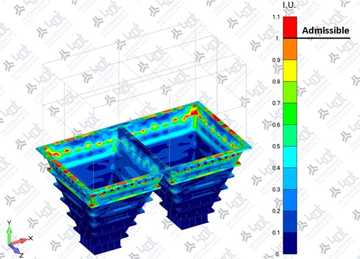
In an ASD method verification, this would be equivalent to a lower overall factor of safety than recommended (standardized). For limit state verification, this information would indicate that the probability of failure is greater than the maximum specified by the standard utilized.
In this sense, based on the LRFD overall methodology, it is shown in Figure 6 that the pre-established quantile for the load magnitude has a value that overcomes that adopted for the resistance.
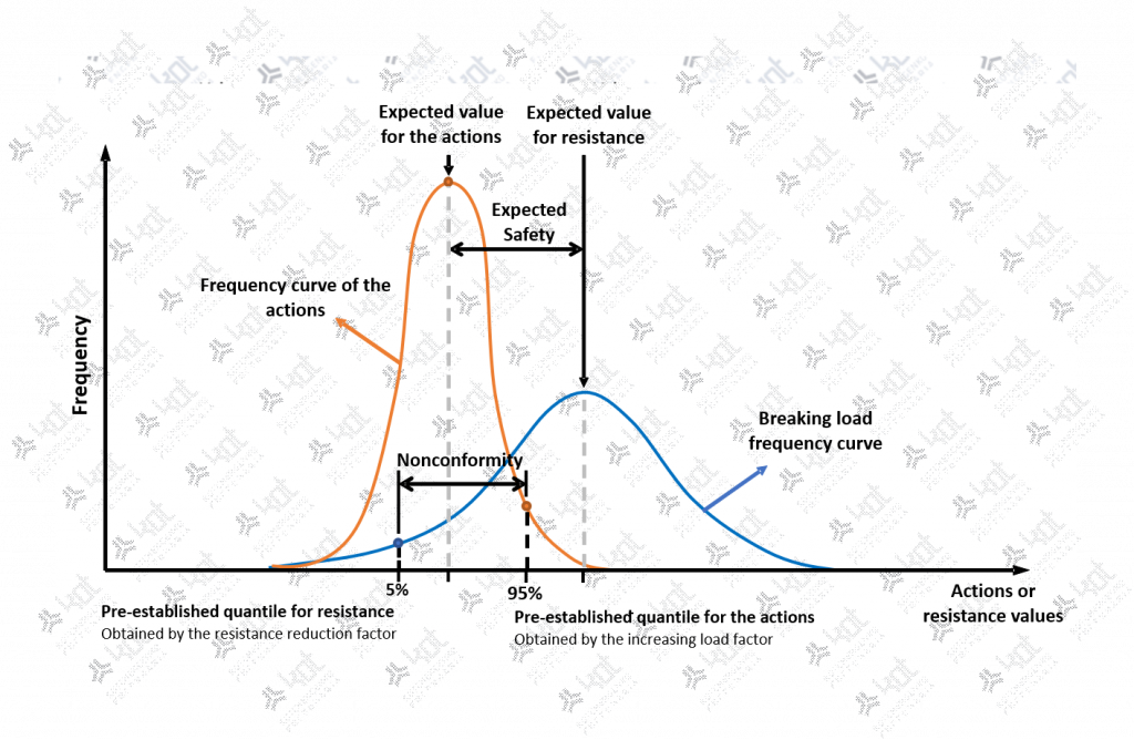
Therefore, a non-compliance condition can be achieved during a normative safety assessment even though the structure has not collapsed, since, according to the standard, this result is ‘only’ pointing to a undesired (higher than desired) risk of collapse. In other words, if a structure is in a nonconformity situation, even though this has not resulted in structural collapse, intervention in the structure becomes necessary in order to reduce the risk of failure.
Conclusion
Considering the concepts and methodologies presented in this article, the importance of structural security becomes even more evident for the protection of assets and structures, in addition to the safety and security of all people involved.
Furthermore, by understanding the methodologies, applications and interpretations of this type of analysis, decision-making becomes even more assertive, obtaining satisfactory results in the areas of quality, safety and productivity.
Finally, if you have needs in structural solutions and safety assessments, Kot Engenharia has specialized skills to assist you. Get in touch with our team!
Recommended bibliography and references
- LOENHARDT, Fritz, MÖNNIG, Eduard. Construções de Concreto: Vol. 1. 1ª Edição, editora Interciência, 1977.
- CHOO, Ban Seng. Advanced Concrete Technology, Science Direct, 2003.
- VAUGHAN, S., FERREIRA, C.B. Numerical Modelling of Wave Energy Converters, Science Direct, 2016.
- CARVALHO, Roberto Chust, FIGUEIREDO FILHO, Jasson Rodrigues. Cálculo e Detalhamento de Estruturas Usuais de Concreto Armado: Vol1. 4ª Edição, Editora EDUFSCAR, 2014.
- ASSOCIAÇÃO BRASILEIRA DE NORMAS TÉCNICAS. NBR 8681 – Ações e segurança nas estruturas – Procedimento, 2003.
- ASSOCIAÇÃO BRASILEIRA DE NORMAS TÉCNICAS. NBR 6118 – Projeto e execução de obras de concreto armado, 2014.
- ASSOCIAÇÃO BRASILEIRA DE NORMAS TÉCNICAS. NBR 8800 – Projeto de estruturas de aço e de estruturas mistas de aço e concreto de edifícios, 2008.
- ASSOCIAÇÃO BRASILEIRA DE NORMAS TÉCNICAS. NBR 7190 – Projeto de estruturas de madeira, 2022.
- AMERICAN CONCRETE INSTITUTE, Committee 318. Building code Requirement for Structural concrete, 2019.
KOT Engenharia’s Team
With over 29 years of history and various services provided with excellence in the international market, the company promotes the integrity of its clients’ assets and collaborates in solutions to engineering challenges. For this integrity, it uses tools for calculation, inspection, instrumentation and monitoring of structures and equipment.


Leave a Reply