Introduction
Currently, the handling and transport of large loads is one of the critical issues facing various sectors of industry. One of the pieces of equipment used to move large and/or heavy products is the overhead crane. In addition, this equipment is easy to use, ensures the safety of the workers involved, and saves a considerable amount of time during handling operations. In this regard, it can be concluded that these machines are indispensable in industrial settings. [1]
Cranes can often be seen installed on the roofs of industrial warehouses. The main components of this equipment are the girders, the trolley and the hoist or winch and their functions are described below.
-
- Beams: structure through which the car will move;
-
- Trolley: mobile equipment responsible for the transverse movement of the load;
-
- Hoist or winch: equipment responsible for lifting and lowering the load.
Check out this article on the work carried out by the Kot team on the structural analysis of a shed extension, with the aim of extending the runway of an overhead crane!
Structural analysis
First, a mining company wanted to extend the travel path of one of its overhead cranes from axis 8 to axis 11 (Figure 1). To that end, it asked Kot to conduct a structural assessment of the warehouse where the crane was installed, in order to ensure that the structure could withstand the modification.
First of all, to provide some context, here are a few definitions used in this analysis.
-
- Utilization index (UI): Evaluates the degree of stress to which a structural element is being subjected;
-
- Permissible utilization index: Value defined in the standard for approving or disapproving the UI found.
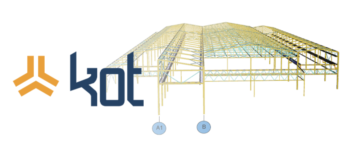
The project began with the modeling of the metal structure using finite elements using PROCAL , software developed by Kot. In addition, the materials used to construct the structure were taken into account during the modeling process. Figure 1 shows the finite elements of the warehouse where the overhead crane is installed.
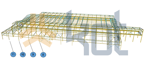
Figure 1: Finite element model of the shed - Axes. [2]
Next, after performing a finite element analysis of the structure in question, the applied loads were analyzed and applied to the model. For example, some of the loads considered are listed below.
-
- Self-weight: These correspond to the forces due to the mass of all the fixed or mobile components of the shed, as well as mechanical and electrical components and support structures;
-
- Wind load: This load case deals with the wind load that the structure is subjected to. The forces are calculated based on the characteristics presented in the standard;
-
- Crane load: Corresponds to the load to which the structure is subjected as a result of the presence of cranes.
Subsequently, after the loads were defined and applied, the structural simulation was performed, and the results are shown in Figure 2.
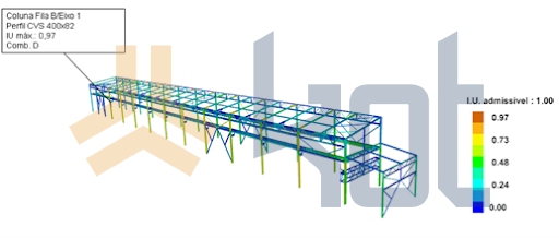
Figure 2: Structural simulation of the shed [2].
Graph 1 shows in detail the utilization rates found compared to the permissible utilization rate.
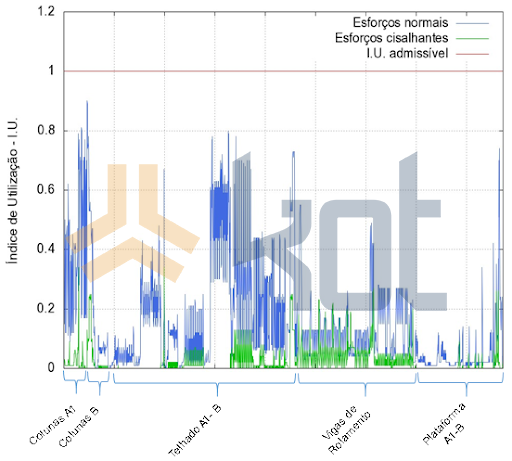
Graph 1: Structure utilization rates. [2]
In addition, connection elements can be defined as those responsible for joining parts of the structure to one another or connecting the structure to external elements. The primary connection methods used are welds, screws, threaded rods, and pins. In summary, we can classify these elements into two groups:
-
- Flexible connection: No resistance to bending moments;
-
- Rigid connection: It presents total restriction to bending moments.
Consequently, the next step in the study was to analyze the connecting elements in the structure, and the results can be seen in Figure 2.
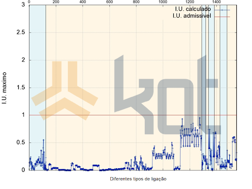
Graph 2: Link utilization rates. [2]
Conclusion
Finally, during the evaluation of the results obtained from the structural and connection analyses, no nonconformities were found; therefore, the length of the overhead crane runway was approved, and the mining company was able to proceed with its warehouse expansion project.
In general, structural analyses are relevant to various areas of industry. This makes it possible to accurately identify the loads and stresses acting on industrial assets and to evaluate the structural behavior of the equipment under these stresses. Consequently, it is possible to identify areas where reinforcements may be necessary. In addition, the Finite Element Method is highly applicable, as it allows for the analysis of complex structures with greater intuitiveness and ease compared to Numerical Methods.
One of Kot’s areas of expertise is structural simulations. The company is capable of operating in a variety of industrial contexts and has in-depth knowledge of the assets found in companies. Contact our team for more information and quotes!
Follow our pages on LinkedIn, Facebook e Instagram to keep up with our content.
FAQ
1. Qual é a função de uma ponte rolante e quais são seus três componentes principais?
A ponte rolante é um ativo industrial utilizado para movimentar cargas de grande porte e alta massa com facilidade, velocidade e segurança. Seus três componentes fundamentais são:
-
Vigas: Estrutura base por onde o carro realiza o deslocamento;
-
Carro: Equipamento móvel que executa o movimento transversal da carga;
-
Talha ou guincho: Mecanismo encarregado da elevação e descida da carga.
2. Qual foi o objetivo da análise estrutural solicitada pela mineradora?
A mineradora desejava aumentar a extensão do caminho de rolamento de uma de suas pontes rolantes, avançando do eixo 8 até o eixo 11 do galpão. O objetivo do estudo foi realizar a avaliação estrutural completa do galpão para certificar se a estrutura metálica suportaria com segurança a nova configuração do equipamento.
3. O que são Índice de Utilização (IU) e Índice de Utilização Admissível?
-
Índice de Utilização (IU): É a métrica que avalia o nível de solicitação ou esforço mecânico ao qual um determinado elemento estrutural está sendo submetido sob carga;
-
Índice de Utilização Admissível: É o valor limite estabelecido por normas técnicas para aprovar ou reprovar a estrutura. Se o $IU$ for menor ou igual ao admissível, o elemento está aprovado.
4. Quais tipos de carregamentos foram considerados na modelagem do galpão?
A simulação computacional considerou três grupos principais de cargas:
-
Peso próprio: Forças decorrentes da massa de componentes fixos, móveis, estruturas de suporte e sistemas mecânicos e elétricos do galpão;
-
Carga de vento: Esforços aerodinâmicos calculados a partir de diretrizes normativas;
-
Carregamento da ponte rolante: Esforços e reações transmitidos à estrutura em função da presença e operação da ponte rolante.
5. Como os elementos de ligação do galpão foram classificados na análise?
Os elementos de ligação unificam partes da estrutura (utilizando soldas, parafusos, barras roscadas ou pinos) e foram divididos em duas categorias:
-
Ligações flexíveis: Conexões que não apresentam resistência aos momentos fletores;
-
Ligações rígidas: Conexões que promovem a restrição total aos momentos fletores.
6. Qual software foi utilizado e qual a vantagem do Método dos Elementos Finitos (FEA)?
A modelagem tridimensional foi realizada no software PROCAL 3D, desenvolvido pela própria Kot Engenharia. O Método dos Elementos Finitos permite mapear e analisar corpos e estruturas industriais complexas com maior precisão e clareza analítica em relação aos métodos numéricos tradicionais.
7. Qual foi o resultado final do estudo para o projeto de ampliação?
Durante a avaliação estrutural do galpão e dos elementos de ligação, não foram encontrados pontos de não conformidade (todos os índices de utilização ficaram abaixo dos limites normativos admissíveis). Dessa forma, a extensão do caminho de rolamento foi aprovada e a mineradora pôde dar prosseguimento às obras de ampliação do galpão.
References:
[1] What an overhead crane is and how it works. Kistler Morse, May 15, 2020. Available at: https://www.kistlermorse.com.br/post/o-que-%C3%A9-uma-ponte-rolante-e-como-funciona
[2] Kot Engenharia Collection.