Success Case: Structural analysis for the expansion of the overhead crane runway
Introduction
Handling and transporting large loads is one of the critical issues in many areas of industry. One of the assets used to move large and/or massive products is the overhead crane. This equipment provides great ease of use, safety for the workers involved, and considerable time savings when performing this handling. With this in mind, it is possible to conclude that these machines are indispensable in industrial contexts. [1]
Bridge cranes can often be seen installed on the roofs of industrial sheds. The main components of this equipment are the beams, the trolley, and the hoist, and their functions are described below.
- Beams: structure through which the trolley will move
- Trolley: mobile equipment responsible for the transverse movement of the load
- Hoist: equipment responsible for lifting or lowering the load.
Check out in this text the work done by KOT’s structural analysis team to extend the runway of a bridge crane!
Structural Analysis
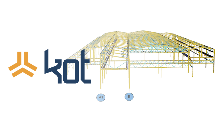
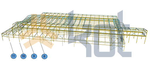
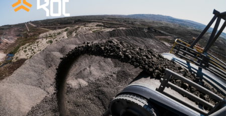
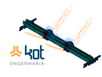
A mining company wished to increase the length of the overhead crane runway, from shaft 8 to shaft 11 (Figure 1), of one of its bridge cranes. To do so, it asked KOT to develop a structural evaluation of the shedin which the asset was installed, in order to make sure that the structure would support the change.
For the best contextualization, here are some definitions adopted for the analysis.
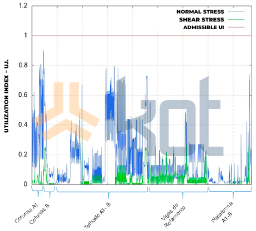
- Utilization Index (UI): Assesses the degree of stress to which a structural element is being subjected
- Admissible Utilization Index: Value defined in the standard to approve or disapprove the UI found.
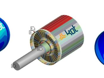
The beginning of the work was given by modeling the steel structure in finite elements with the help of the software, developed by KOT, PROCAL 3D. During the modeling the materials in which the structure is built were considered. Figure 1 shows the finite element model of the industrial shed where the overhead crane is installed.
After performing the finite element modeling of the structure in question, the acting loads were studied and applied to the model. Some of the loads considered are listed below.
- Self Weight: Corresponding to the forces due to the mass of all fixed or movable components of the industrial shed, as well as mechanical and electrical components and support structures
- Wind load: This loading case deals with the wind load that the structure is subjected to. The loads are calculated based on parameters presented in the standard
- Overhead Crane Loading: This corresponds to the loading to which the structure is subjected due to the presence of bridge cranes.
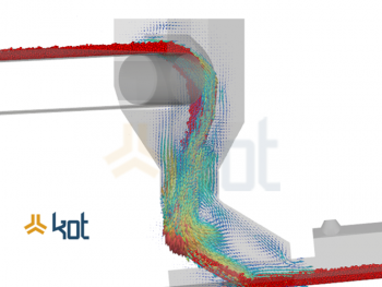
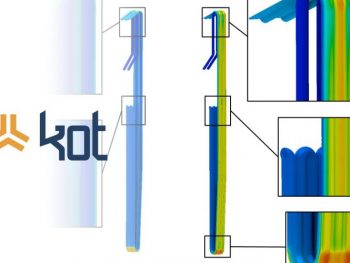
After the loads were defined and applied, the structural simulation was performed and the results can be seen in Figure 2.
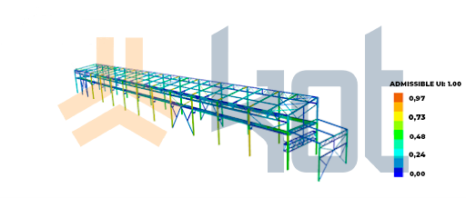
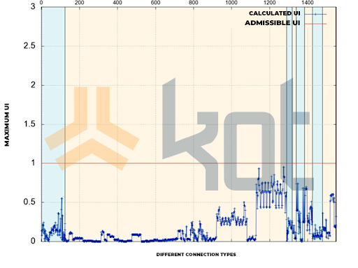
Chart 1 shows in detail the utilization indexes found compared to the admissible utilization index.
It is possible to define connecting elements as those responsible for promoting the union of parts of the structure with each other or of the structure with external elements. As means of connection are mainly used welds, bolts, threaded rods, and pins. In short, we can classify these elements in two groups:
- Flexible connection: No resistance to bending moments
- Rigid connection: Presents total restriction to the bending moments.
The sequence of the work was given by the analysis of the existing connecting elements in the structure and the results found can be seen in Chart 2.
Conclusion
During the evaluation of the results obtained by the structural and connection analyses, no points of non-conformity were found, therefore the overhead crane runway extension was approved and the mining company could proceed with its project.
Structural analyses are relevant to several areas of industry. With these studies, it is possible to accurately identify the existing stresses in industrial assets and evaluate the structural behavior of the equipment against the loads. With this, it is possible to point out points for reinforcements that may be necessary. The Finite Element Method presents great applicability, because with it it is possible to analyze complex bodies with greater intuitiveness and ease with respect to the Numerical Methods.
One of KOT’s specialties is structural simulations. The company is able to act in several industrial contexts and masters knowledge about the assets present in companies. Contact the team for more information and quotes!
Get in touch with KOT’s specialists team!
KOT Engenharia’s Team
With over 29 years of history and various services provided with excellence in the international market, the company promotes the integrity of its clients’ assets and collaborates in solutions to engineering challenges. For this integrity, it uses tools for calculation, inspection, instrumentation and monitoring of structures and equipment.
References:
[1] O que é uma ponte rolante e como ela funciona. Kistler Morse, May 15, 2020. Available at: https://www.kistlermorse.com.br/post/o-que-%C3%A9-uma-ponte-rolante-e-como-funciona
[2] KOT Engenharia Collection.


Leave a Reply