Succesful Case: Structural and mechanical analysis of a bridge reclaimer
Introduction
Structural analysis using the finite element method (FEM) is a resource widely used for structural integrity assessment of industrial assets. As an example, the analysis can be applied to yard machines to check for non-conformities, possible failures and unknown phenomena.
Structural Analysis
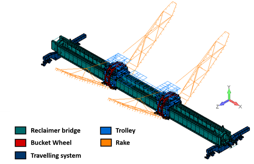
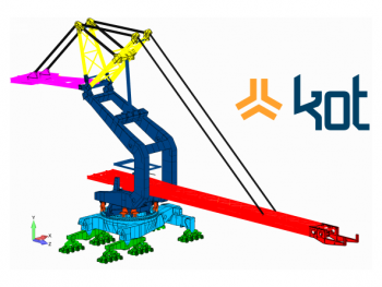
Kot carried out the structural validation of a reclaimer using the finite element method (FEM). The iron ore reclaimer, which has a design capacity of 1950 tons per hour, is of the crane type and has two bucket wheels for material recovery.
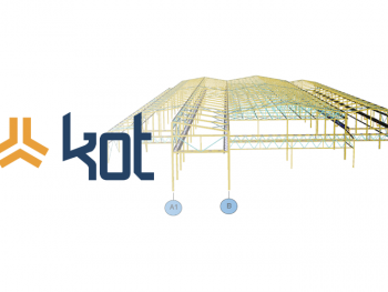
Structural verification begins with the elaboration of a finite element model of the machine in CAE (Computer Aided Engineering) software, accurately reproducing the geometry of the asset. The generated model can be seen in Figure 1.
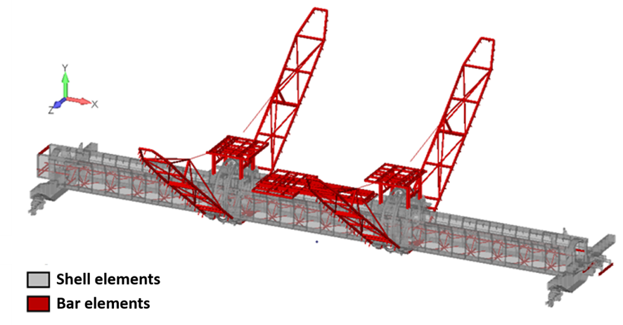
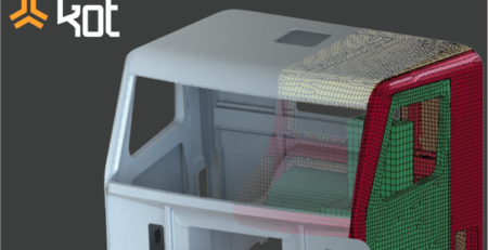
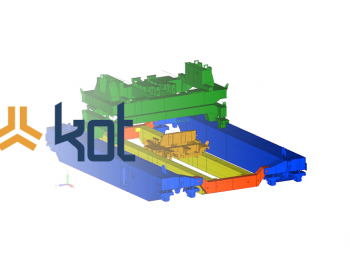
In the model, profiled components are represented as bar elements, while those formed by plates are represented as shell elements, as illustrated in Figure 2 below.
In operation, yard machines work with high loads from the equipment’s own weight, the material load on the belt conveyor, the wind load, the incrustation load, etc. Therefore, after the model is generated, the loads acting on the structure are identified and grouped in load combinations.
With FEM, these combinations of loads are discretized and applied to the arrangement of the equipment for structural verification under different operating conditions, as recommended by the standard. After that, for the machine in question, static, modal, buckling, fatigue and connections analyzes were carried out, and the results of each of them are interpreted according to normative criteria.
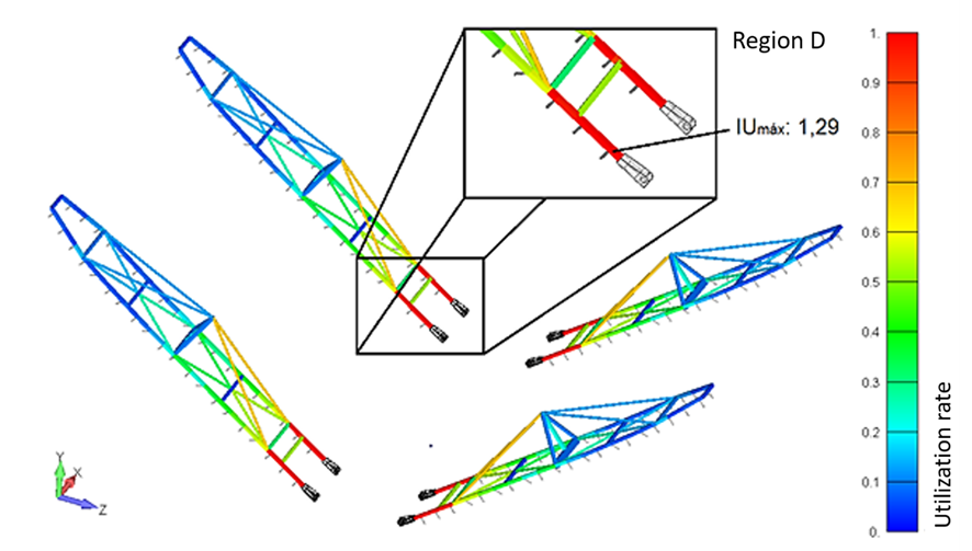
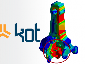
The static analysis of the machine is performed considering the efforts obtained in the finite element model. Allowable stresses, safety factors and specific utilization rates are considered for each component of the structure, depending on the load combinations applied and evaluated. In the analysis of the reclaimer’s bar elements, utilization rates above the admissible are identified at the rear of the rake, as highlighted in region D of Figure 3 below.
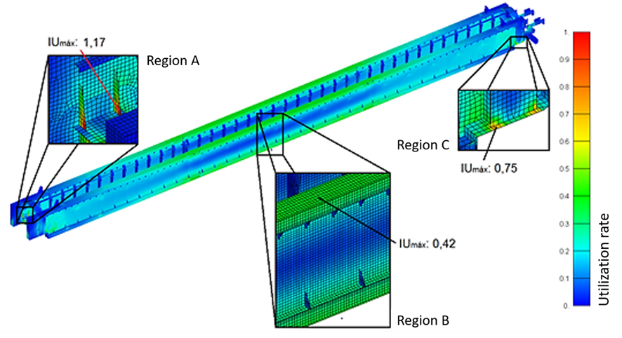
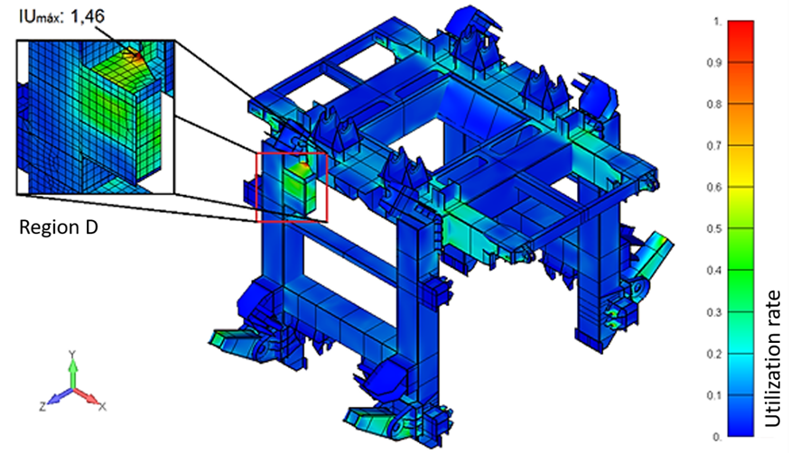
Regarding the static analysis of the shell elements, utilization rates above the permissible are observed in the bridge ribs (region A of Figure 4) and in the stretcher support of the travelling car (region D of Figure 5).
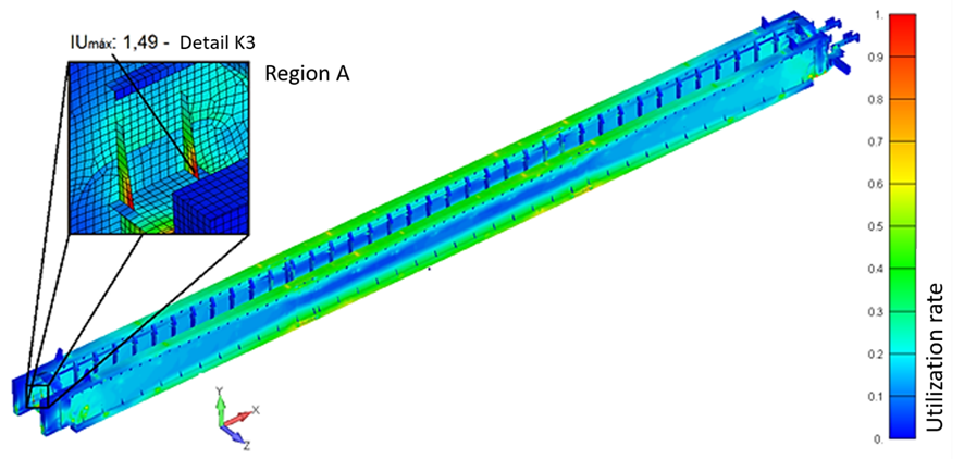
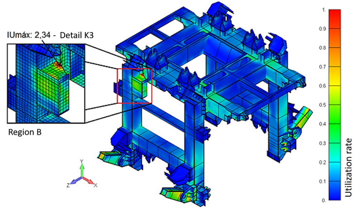
In the fatigue analysis, a normative evaluation methodology was adopted for the useful life of the shell elements, which considers the existing stress concentrators and the predictions of the number of cycles, the magnitude of actions and the variation of stresses in each element. As a result, Utilization rates above the admissible were verified at the same points accused by the static analysis, as can be seen in Figure 6 and Figure 7.
In the analysis of local buckling of thin plates, stressed mainly by compression, the critical loads were calculated. For the reclaimer were considered the type of acting effort, boundary conditions, geometric parameters, material properties, values of acting stresses, etc. The results obtained were within the permissible limits for all loading cases evaluated.
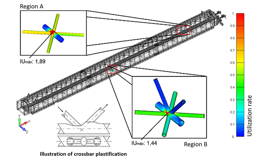
Connections, commonly classified according to their rigidity, were also analyzed according to standards. Thus, utilization rates above the admissible were observed in the connections of some of the bridge’s tubular braces, mainly due to the acting of wind loads in service and out of service on the machines (the most critical condition for the structure). The loads acting on the connections (for the machine out of service condition) can be seen in Figure 8.
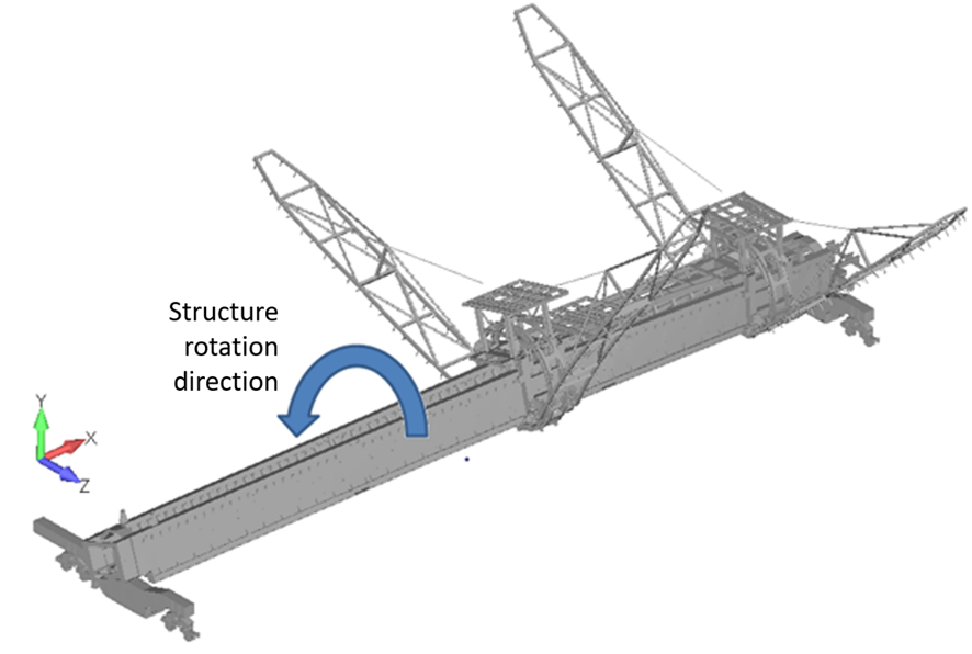
In the modal analysis, the possibility of structure resonance was verified. The frequency of material discharge on the impact rollers of the crane belt conveyor was considered as the source of excitation. Therefore, the risk of resonance was identified in one of the natural vibration modes of the structure (Figure 9), which is characterized by the rotation of the bridge and the travelling cars around the longitudinal axis of the machine. Through this, it was found that the vibration speeds can exceed the admissible limits.
Finally, from the results obtained through the FEM analysis of the machine points of attention were raised, in which inspection is necessary to investigate the conditions of the asset in order to determine or not the need for corrective actions.
Due to the risk of failure in the rear part of the rake (in the ribs of the transverse beam supporting the bridge and in the support of the stretcher of the chain that drives the bucket wheel) reinforcements were proposed to adapt the structure of the reclaimer to the normative criteria, correcting the nonconformities found.
Mechanical analysis
Mechanical analysis is used to verify the operational function of mechanical components. It is also relevant to machine design due to the sizing of systems based on analytical and numerical calculations.
In this sense, Kot carried out the mechanical verification of the belt conveyor of the iron ore reclaimer. The model used in the analysis can be seen in Figure 10.
In the analysis, the capacity of the conveyor in question was verified in order to assess the possibility of material overflow during its operation. It was then verified whether the respective belt withstands the stresses applied to it by means of its rupture tension. Other parameters related to the belt were also evaluated at this stage, such as transition distance, vertical curves, flapping, among others.
In addition, the required power was analyzed in order to assess whether the belt conveyor drive system was able to meet the design capacity. The sizing of its mechanical components such as motors, couplings, reducers, brakes and backstops were also checked based on the catalogs of the respective manufacturers and also on the highest required and/or installed power. Along with the conveyor drive system, the sizing of the rollers and drum shafts was also verified.
According to the analysis of the crane belt conveyor, it was observed that the tension value on the slack side of the drive pulley is lower than the minimum admissible during braking with loaded material. According to the standard, this factor can lead to the belt slipping in relation to the drive pulley. On the return roller shafts, a deflection greater than the admissible limits established by the manufacturer and by standard was observed. As a result, these components were not approved.
Besides the belt conveyor and the bucket wheel, the machine, trolley and rake tipping travelling systems were also analyzed. As a result, the braking moment of the machine’s travel system, in certain cases, is insufficient to stop it, in addition to the driving travelling wheels not being able to transmit the braking force without slipping with the rail. Furthermore, the mechanical service factor of the bucket wheel reducer is lower than the minimum recommended by the manufacturer. No nonconformities were found in the trolley’s travelling and rake tipping systems.
Finally, based on the results obtained through the mechanical analysis of the machine, it was recommended to increase the current counterweight and check in field if there is a rail-lock system to assist braking during out of service wind action. If not, the installation of this device was recommended as a corrective measure.
Conclusion
Therefore, it was noticed that when using the finite element method for the structural analysis of yard machines, an evaluation with high reliability is obtained regarding the structural perspective of the asset. Thus, through this calculation method, it is necessary to be aware of the boundary conditions, mass and position of non-modeled components, constraints, among other examples. Furthermore, it is important to know the magnitude and types of loads expected for the equipment during its useful life, as well as the standards that recommend each type of analysis.
Similarly, greater assertiveness is obtained regarding the operational functioning of the machines when resorting to mechanical analysis. Also, this extends to assessing the condition of its mechanical components and sizing the respective systems.
Kot has trained professionals to understand and evaluate the best solutions for the day-to-day engineering challenges of the industry, such as for structural and mechanical analyzes of yard machines. Contact our team for more information!
KOT Engenharia’s Team
With over 29 years of history and various services provided with excellence in the international market, the company promotes the integrity of its clients’ assets and collaborates in solutions to engineering challenges. For this integrity, it uses tools for calculation, inspection, instrumentation and monitoring of structures and equipment.


Leave a Reply