Successful implementation: Structural analysis of a reclaimer
The structural analysis of material equipment handling using the Finite Elements Method (FEM) is an important tool in the promotion of an asset’s structural integrity. It can be applied, for instance, to verify eventual project issues, investigate non-foreseen or unknown phenomena and offer technical support for planning and maintenance.
To better understand the method applied in large-sized reclaimer or stacker in order to handle bulk, learn more about successful implementation cases carried out at KOT Engineering. To review basic concepts about FEM, check out the article: Understanding Finite Elements Method.
Structural analysis of a reclaimer
KOT was responsible for the structural validation, using FEM, of a reclaimer in around 1800 tons and the process capacity of nearly 11000 tons/hour. It is one of the assets responsible for handling sinter e pellet feed in a client’s facility.
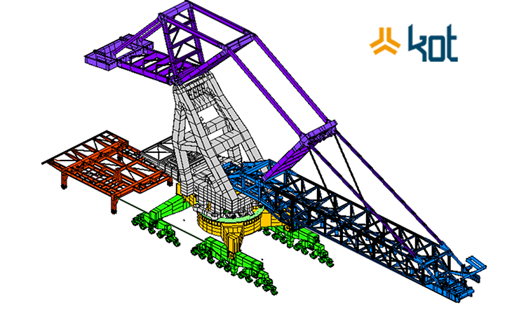
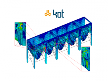
Initiated by the computational modeling of the asset in a CAE (Computer Aided Engineering) software, the analysis using the finite elements method takes place in a software environment. It is possible to create a tridimensional model reproducing the exact geometry of the asset. Right below, in Figure 1, we can see the generated model of the Reclaimer and its component division.
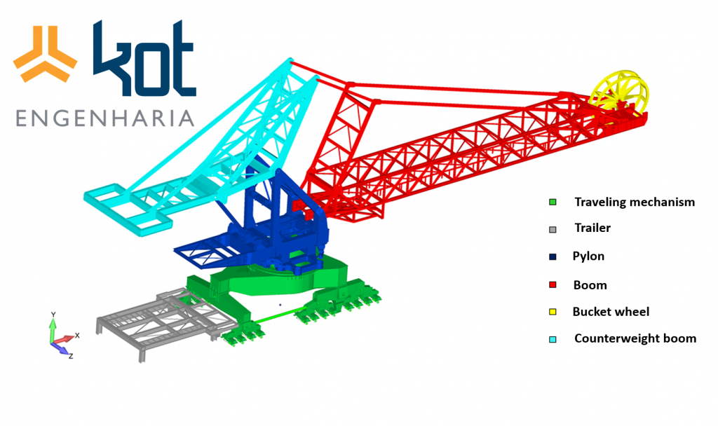
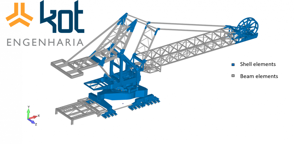
Figure 2 brings us a different representation, indicating the shell and beam elements used in the elaboration of this model.
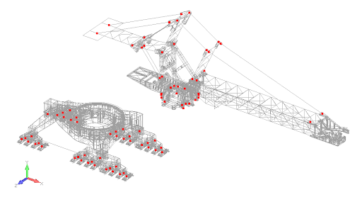
Material handling equipment of this kind work under high load rates, arising from the equipment’s own weight, the added load due to the wind, as well as the operation loading. The FEM analysis allows the discretization and application of these loads over the structural arrangement of the equipment. Starting from the applied loads, the static, buckling fatigue, connections, stability and modal analysis are elaborated. The results are interpreted according to the criterion established by standards.
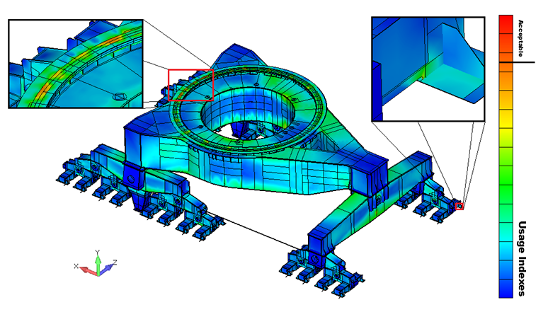
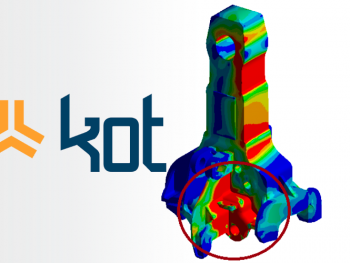
In the static analysis the reclaimer in question specific standard criteria were adopted for the elements under different tension envelopes and usage indexes (UI) for each load combination. In the analysis of the bar elements, the usage indexes were not found to be above the allowed level. In the analysis of the shell elements, it was observed that, in certain regions of the counterbalance, UIs of the structure which exceed normative values were obtained, as shown in figure 3.
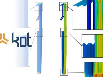
In the fatigue analysis, the normative evaluation methodology was used for the lifespan of the project and its defined loaded cycles. At this stage it was considered that the ore loaded equipment was subject to operation movements such as tilting, translation and rotation. As a result, regions with maximum UIs within the allowable range were observed, in the region of the machine portal, as shown in Figure 4.
In the analysis of local buckling of the main plates of the reclaimer, the admissible requests were verified according to the established criteria. These regions are typically required for compressive loads, which can generate the effect of local elastic failure of certain components. In this reclaimer, the regions were analyzed and verified, considering the stresses, material parameters and boundary conditions. The results found were within the acceptable range.
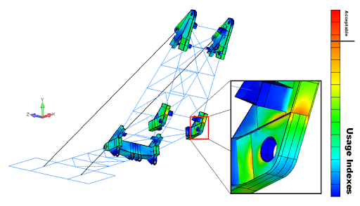
The connections were analyzed according to normative criteria pre-established by the analytical method. The importance of checking connections is emphasized, considering the types of connections existing in the equipment, whether rigid, flexible or pinned. The calculated results were also below the permissible utilization rates. Some of the connections are shown in figure 5.
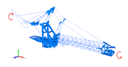
In the modal analysis, the structural resonance potential was evaluated, considering the exciting sources such as wind and rotating elements of the equipment. In the analysis the risk frequencies were assessed for the different natural vibration methods. In one of the modes, it was identified – with warnings – the risk of resonance, arising from some rotating elements of the equipment’s conveyor belt. One of the equipment’s natural vibration modes can be seen in figure 6.
Finally, points of focus and the need for inspections during the maintenance of the asset were indicated. Although some utilization rates are above the allowable, it was not necessary to propose reinforcements for the structure.
When solving engineering problems using the Finite Elements Method, it is necessary to know the norms that establish the appropriate criteria for each type of analysis, as well as to adequately define the boundary conditions, restrictions, mass and position of non-modeled components. it is necessary to measure and analyze the stresses to which the equipment is subjected during its lifespan. Through this calculation method, development and evaluation with high reliability are promoted, mainly regarding the perspective of the structural integrity of the asset.
Get in touch with KOT’s specialists team!

Aender Ferreira
Mechanical Technician from CEFET-MG, Mechanical / Aeronautical Engineer from UFMG and Master in mechanical projects from the same university. Before graduation, he had experiences in the mining, maintenance, project design, experimental engineering and automotive industries. As an Engineer, he started his career in the maintenance sector performing calculus activities for fatigue in aeronautical components and structures. Subsequently, he was invited to compose the Board of Directors of KOT Engineering, working in the commercial sector of the company, helding the position for almost 15 years.


Leave a Reply