Successful Case: Failure analysis of a crusher shaft
Introduction
Crushing is a set of operations carried out to fragment ore b locks of various sizes, which can be segmented into stages such as primary and secondary. The machines most used during this process are crushers, which come in various types such as gyratory, jaw, impact, and roller crushers.
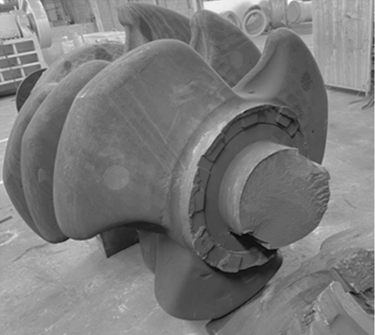
This article discusses one of Kot’s successful cases, in which the failure analysis of the driven shaft of a roller crusher (Figure 1 shows the fractured shaft) was performed. The system is composed of a set of 9 rotors, each formed by three teeth, and the shaft is driven by an electric motor system connected to a hydrodynamic coupling.
In order to determine the causes of the failure, Kot performed a structural evaluation of the shaft, using visual inspections, laboratory and computational analysis using the Finite Element Method (FEM).
Methodology
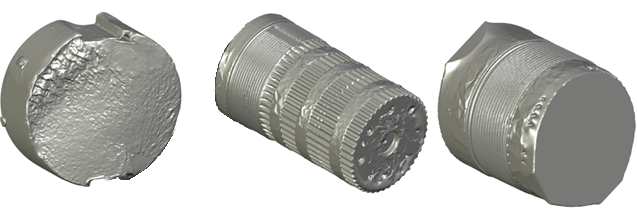
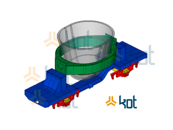
The activity began with the realization of the as built of the crusher shaft, through 3D scanning of the fractured structure, as well as the dimensional surveying. The scanned shaft model can be seen in Figure 2.
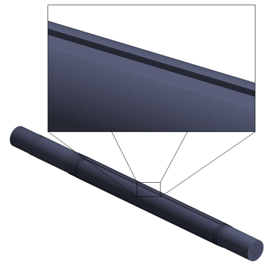
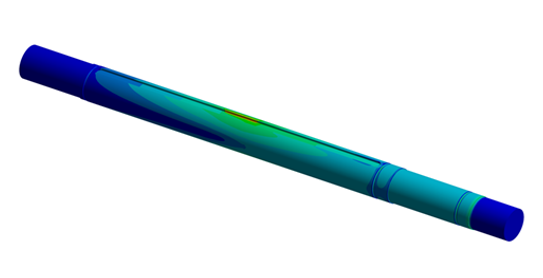
The finite element model was generated in a specific software. For mesh generation, a combination of second-order tetrahedral and hexahedral solid elements was used. The shaft’s failure region was modeled with a higher mesh refinement, aiming to achieve a better computational cost-to-precision ratio for calculating the acting stress field. Figure 3 presents the elaborated finite element model.
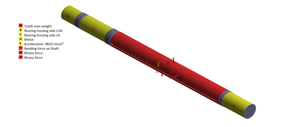
Just as the correct determination of the discretization of the continuous medium, the application of boundary conditions is also crucial for obtaining reliable results for the reality of the simulated object. Constraints were applied to the model to represent the contact between the shaft and the radial bearings and the contact of the splined portion with the drive system reducer. The loads generated by the contact of the teeth with the material to be crushed were applied as remote loads to account for the bending and torsional moments.
Several operating conditions were simulated in order to cover the widest range of stresses acting during a rotation of the shaft, as well as to account for the various load cycles that the equipment is exposed to during its lifetime. The variation of tooth positions and load magnitudes considered allows the performance of a fatigue analysis with a load spectrum closer to reality.
Figure 4 illustrates the boundary conditions for one of the simulated operating situations.
Results
After the construction of the computational model, static analyses were carried out using the Finite Element Method (FEM). For all situations, including the maximum torque (see Figure 5), the shaft structure presents a safety factor higher than that suitable for the type of application, indicating that the structure is able to withstand the static loads.
The second stage of the failure analysis was the fatigue verification of the shaft. Based on the motor current history recorded by the automation system, the load cycle counting was performed using the rainflow methodology, as recommended in international standards.
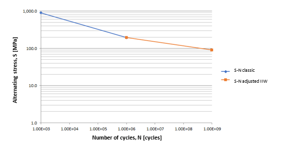
Due to the crusher’s operating mode, a non-reversible multiaxial stress state is generated, requiring the use of a specific fatigue analysis methodology. The classic S-N diagram indicates a constant plateau after 106 cycles, but according to an international standard, steels in components subjected to a high number of cycles do not exhibit such a plateau. Therefore, the angular coefficient of the S-N curve was altered after 106 cycles to reflect this behavior, as shown in Figure 7. Based on the S-N curve and the number of cycles to which the shaft was subjected before failure, a safety factor higher than recommended was also obtained, indicating that the shaft’s failure due to fatigue was not expected.
To better understand the cause of the failure, a detailed analysis of the fracture surface was performed, which confirmed the presence of several cracks near the keyway, resulting from previous maintenance interventions on the shaft. The coalescence of these cracks generated a macro crack, which underwent fatigue propagation and compromised a percentage of the cross-sectional area of the shaft before the failure. Due to this finding, the possibility of overload failure during operation was raised.
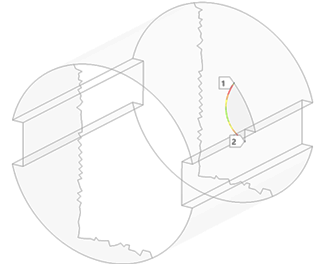
In order to understand the magnitude of the load that caused the failure, a Linear Elastic Fracture Mechanics analysis was performed, in which a crack with dimensions similar to those observed on the fracture surface was introduced into a finite element computational model. This allowed for the calculation of the Stress Intensity Factor (SIF) at the crack tip and comparison of this parameter with the Fracture Toughness (KIC) of the material.
Based on the simulations carried out, it was observed that loads equivalent to the maximum torque of the drive motor were capable of causing the combined SIF for traction and torsion modes to equal the KIC of the material, resulting in the fracture of the shaft. Figure 8 illustrates the distribution of the Stress Intensity Factor at the crack tip in the computational model.
Conclusion
Based on the analyses carried out, it was concluded that the shaft design was adequate for the operating loads. However, due to the inclusion of defects resulting from maintenance interventions on the shaft, a crack was generated, which propagated stably by fatigue until the material reached the fracture toughness during an overload event, resulting in brittle fracture of the shaft.
Kot’s team has experts in asset structural integrity, so feel free to contact us for more information!
KOT Engenharia’s Team
With over 29 years of history and various services provided with excellence in the international market, the company promotes the integrity of its clients’ assets and collaborates in solutions to engineering challenges. For this integrity, it uses tools for calculation, inspection, instrumentation and monitoring of structures and equipment.


Leave a Reply