
Extensometry is a method of experimentation that aims to measure deformations and, consequently, obtain stresses in components, structures and equipment. This is done by installing sensors that are fixed to the surface of the object under study, called strain gauges.
To apply this methodology, one must understand the theory behind how it works. In the article Basic principlesof Extensometry – Part 1, we presented how Hooke's Law relates the deformations of a material to the stresses applied to it, which is the basis for studies using extensometry. In this second part, learn more about extensometers, the principles of their operation, and the main types found on the market.
The strain gauge structure
Strain gauges are sensors based on electrical resistance, behaving like a resistor. It is glued to the component being studied, and when it is subjected to deformation in a certain direction (with one, two or three axes), a potential difference is generated in the sensor.
Basically, the sensors are made up of a grid of conductive material deposited on an insulating adhesive compound. When glued to a body that is being deformed due to the application of a load, the strain gauge undergoes deformation. As a result, the meshes increase in size, generating a variation in the initial resistance of the strain gauge. By applying a constant electrical voltage to the terminals of the strain gauge and varying the resistance with linear deformation, it is possible to obtain the current variation of the closed system. [1]
The metal grid of the strain gauges is sensitive, and the base to which it is connected adheres to the part or structure you want to monitor. In most commercial strain gauges, the sensitive wire has a diameter of approximately 0.1 mm and is made from special metal alloys. The grid is embedded inside a thin plastic film or between two (2) sheets of paper. Examples of uniaxial and triaxial strain gauges are shown in Figure 1.
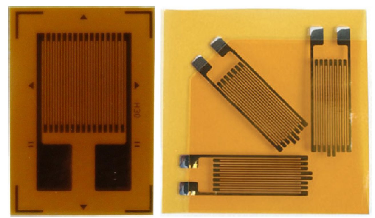
Figure 1: Uniaxial extensometer (left) and triaxial or rosette (right) - SOURCE: SILVA (2019).
The principle of electrical conductance
The operation of the strain gauge is basically based on the principle of electrical conductance and depends very much on the geometry of the structure being analyzed. It is simply designed based on the phenomenon that the specific length of a given resistance wire is directly proportional to the resistance of the wire, as shown in Equation 1 [3].
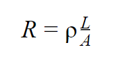
Equation 1: Calculation of electrical resistance - SOURCE: BESTECH (2019).
Where:
R = resistance of the wire;
ρ = resistivity;
A = cross-sectional area of the specific wire.
Assuming that when the wire is pulled the cross-sectional area is reduced, using Equation 1 we obtain Equation 2.
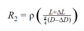
Equation 2: Calculation of the new resistance - SOURCE: BESTECH (2019).
Where:
R2 = is the new resistance generated due to the change in dimensions and is also called the deformed resistance;
D= diameter of the object;
∆D = variation in the diameter of the object.
From the deformation equation –which can be seen here– replacing ∆L with the variation in the resistance of the extensometer due to tension and L with the resistance factor inherent to the extensometer, we obtain Equation 3:
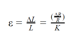
Equation 3: Strain calculation - SOURCE: BESTECH (2019).
Being:
∆R = Variation in strain gauge resistance due to deformation;
R = resistance of the strain gauge;
K = strain gauge measurement factor.
Wheatstone Bridge
In general, it can be seen that a strain gauge works on the basic principle of a simple metal conductor wire that tends to vary in its length, cross-sectional area and resistance due to a given applied voltage.
Extrapolating from this concept, all strain gauge configurations are based on the concept of a Wheatstone bridge, which is a network of 4 resistors. Simply put, one or more of these legs can be active sensing elements. In short, a Wheatstone bridge is a voltage divider circuit, as shown in Figure 2, which can detect small changes in resistance.
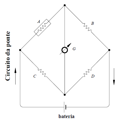
Figure 2: Typical diagram of a Wheatstone bridge - SOURCE: ANDOLFATO, CAMACHO and BRITO (2004).
This bridge is the electrical equivalent of 2 parallel circuits. In this sense, RA/RB and RC/RD make up these two circuits, and the voltage is measured at the output. The output of a Wheatstone bridge is measured at the interface.
A physical phenomenon, such as a change in the deformation applied to an object being monitored or a change in temperature, alters the resistance of the sensing elements in the Wheatstone bridge. As such, its configuration is used to help measure small variations in resistance. This variation in resistance that the sensing elements produce induces a variation in voltage which, in practice, corresponds to a physical change in the object being measured/monitored.
Basically, there are three types of strain gauge configurations: ¼ bridge, ½ bridge and full bridge. Each of these configurations is subdivided into several subtypes. Two examples can be seen in Figure 3 and 4.
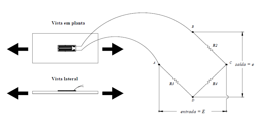
Figure 3: Measurement with traction using ¼ bridge - SOURCE: ANDOLFATO, CAMACHO and BRITO (2004).
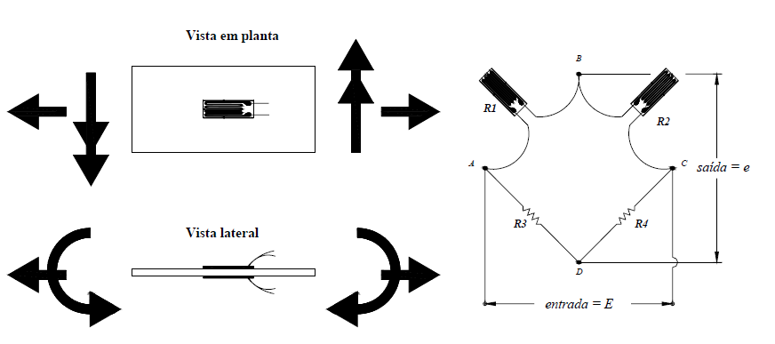
Figure 4: Bending measurement using ½ bridge - SOURCE: ANDOLFATO, CAMACHO and BRITO (2004).
Types of strain gauge
There are many types of strain gauges and their choice must be made according to various criteria. These criteria include the level of deformation, the temperature at which the monitoring is being carried out, the material of the object, the environment, the geometry, the manufacturer, the use, among other factors. The literature and manufacturers provide various classifications and types of strain gauge for use. Table 1 shows some of the most common types of extensometers that can be used for extensometry.
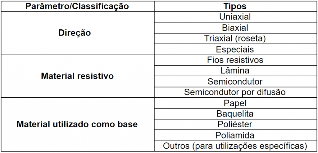
Table 1: Types of extensometer - SOURCE: ANDOLFATO, CAMACHO and BRITO (2004).
The possibilities for using extensometry for Structural Integrity solutions Structural Integrity vast. However, it is important to note that there are also limitations to the use of this tool. In some situations, its use is not the most appropriate, and there are more suitable options depending on the needs of the study. In certain cases, it is recommended to use only finite element analysis (FEA). In others, a combination of FEM and extensometry is recommended.
Kot has extensive experience in this field and can provide its customers with extensometry solutions for testing and monitoring to promote Asset Integrity. Consult our team for more information!
Follow our pages on LinkedIn, Facebook e Instagram to keep up with our content.
References:
[1] SILVA, Anderson Langone et al. A study of strain and deformation measurement using the Arduino microcontroller and strain gauges devices. Revista Brasileira de Ensino de Física, v. 41, n. 3, 2019.
[2] BIELEN, Paul; LOSSIE, Mieke; VANDEPITTE, Dirk. A low cost wireless multi-channel measurement system for strain gauges. In: Proceedings of ISMA. 2002. p. 663-670.
[3] BESTECH. UNDERSTANDING THE FUNDAMENTALS OF STRAIN GAUGE. 16-09-2019 Available at: https://www.bestech.com.au/blogs/strain/understanding-fundamentals-strain-gauge/. Accessed on: March 3, 2021
[4] ANDOLFATO, R. P., CAMACHO, J. S., de BRITO, G. A., Basic Extensometry, (NEPAE UNESP, Ilha Solteira, 2004)


