
Introduction
In general, ore slurry tanks are equipped with agitators to homogenize the slurry before it is pumped to the next stage of the ore processing. As such, these agitators introduce cyclic forces to the tank walls which, depending on the tank’s geometry, the agitator’s rotational speed, and its power, can cause excessive vibrations in the equipment. As a result, these vibration levels can drastically reduce the asset’s service life and create a high risk of collapse due to crack propagation. Thus, in cases like this, vibration analysis using tank imagery can provide crucial information for assessing the situation, helping to propose corrective measures to mitigate the problem.
Case
Initially, the client observed that its tanks, under specific conditions regarding pulp level and agitator speed, exhibited significant vibration amplitudes visible to the naked eye. As a result, this vibration caused cracks in the concrete base after only a short period of tank operation. Therefore, Kot was hired to assess potential damage to the metal structure and propose solutions to mitigate the problem.
To measure equipment vibration in the field, Kot utilized motion amplification technology provided by RDI Technologies’ IRIS MTM camera. Furthermore, using the IRIS camera for this application is highly advantageous, as it allows for the measurement of vibration at various points on the tank in just a few minutes, determining the tank’s vibration frequencies and displacements at various specified points on the structure. For more details, learn about vibration analysis via imaging by clicking here.
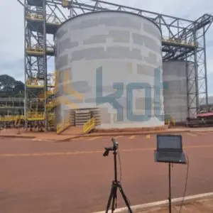
Figure 1: Vibration measurement with the IRIS camera.
Furthermore, it is possible to determine the specific vibration mode of the structure using just a few measurements taken around the tank. To determine this vibration mode using traditional measurement methods, such as accelerometry, it would be necessary to install several accelerometers simultaneously around the entire tank. In this case, that would be impractical due to the time required to install the sensors on the tank and the time required to process the signals.
Figure 2: Tank vibration - IRIS camera.
For example, in the figure below (Figure 3), you can see a magnified image of the tank’s vibration captured by the IRIS camera.
Figure 3: Amplified vibration of the tank - IRIS camera.
In addition, it was observed that the vibration caused the bottom of the tank to rise relative to the concrete foundation, as shown in Figure 4 below:
Figure 4: Survey of the tank bottom – IRIS camera.
Next, the vibration data collected in the field were used to calibrate a forced vibration analysis performed using the finite element method (FEM). Thus, the FEM analysis provided displacement, stress, and strain data for all points on the tank, making it possible to measure the effects of the vibration observed in the field on the structure.

Figure 5: Forced vibration analysis.
Consequently, a high-cycle fatigue analysis of the tank structure showed that the vibration conditions measured in the field are severe enough to reduce the tank’s service life. Under these conditions, if the equipment operates for approximately 200 hours, there is a risk of cracks developing in the side welds, compromising the Structural Integrity asset.
Solution
Accordingly, the solution proposed was a change in the tank’s operating procedure. For pulp levels critical for vibration, a reduction in the agitator’s rotational speed was proposed. This measure shifts the frequency of the excitation source away from the structure’s natural frequency, reducing vibration on the tank sidewall by approximately 40 times. Consequently, with this modification, no cracks are expected to form in the structure during the asset’s service life.
It is worth noting that this simple modification does not affect the client’s operational productivity, since the new speed selected for the agitator does not compromise the homogenization quality of the pulp. Furthermore, it avoids costs associated with installing reinforcements, which include both the construction costs and lost profits due to the asset’s downtime.
Consult our team for more information!
Follow our pages on LinkedIn, Facebook e Instagram to keep up with our content.


