
Introduction
First, this article will discuss a project carried out by the company’s team to analyze an overhead crane. In addition, during the study, the team conducted visual inspections, non-destructive testing, strain gauge measurements, structural analysis, and an analysis of the asset’s repowering.
The overhead crane in question consists of two outer main girders, two inner main girders, two connecting girders, a main hoist trolley, an auxiliary hoist trolley, and the travel system. The primary function of this equipment is to transport and tilt ladles containing molten iron for the steel production process. Figure 1 shows an overview of the crane.
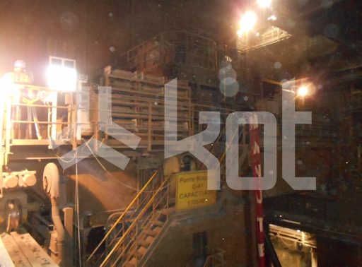
Figure 1: General view photograph of the crane. [1]
Figure 2 shows the views of the technical drawing of the asset with an indication of the systems that make up the machine.
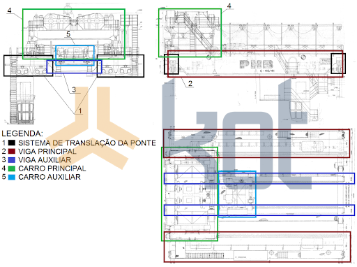
Figure 2: Crane subdivision. [1]
Field Services
First and foremost, the field services were aimed at inspecting the Structural Integrity overhead crane, identifying nonconformities in order to recommend possible measures necessary to ensure the equipment’s safe operation. To this end, the condition of the structures was assessed using visual inspection, ultrasonic testing, and penetrant testing.
-
- Visual inspection
First, a visual inspection was conducted to assess the equipment’s overall condition, looking for signs of corrosion on the structure. In addition, the main welded joints were inspected, and an evaluation was performed to identify any deformed profiles or plates, as well as design modifications.
During that inspection, for example, several nonconformities were identified, some of which are listed below.
Figure 3 shows a weld at the head of the auxiliary beam in which the weld bead was not completely filled, while Figure 4 identifies a deformation in the main car stop.
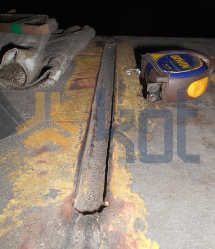
Figure 3: Weld with lack of fusion detected at the head of the auxiliary beam. [1]
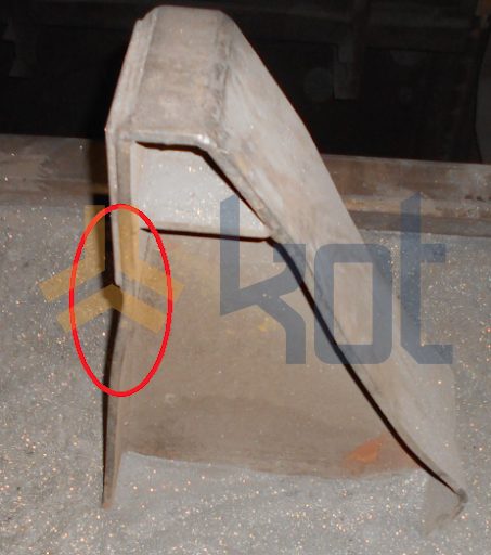
Figure 4: Deformation at the main carriage stop. [1]
On the other hand, components that met the expected standards were also found and documented during the visual inspection. Figure 5 shows the wheel of the auxiliary car.
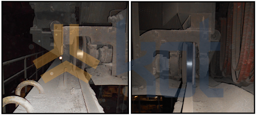
Figure 5: Position of the trolley wheel. [1]
Subsequently, upon completion of the visual inspections, Kot indicated that the best course of action regarding the deviations observed would be to await the Technical Report structural analysis to verify the sizing of the structural members. For the structural members found to be within the expected parameters, a periodic inspection plan was recommended.
-
- Extensometry
Next, strain gauge analysis was performed at various stages of a controlled operation, which made it possible to evaluate the deformation at specific points on the structure. During the test, the overhead crane was moved several times in order to calibrate the computational model using a standard load of known mass.
Figure 6 shows the graph containing the results obtained during extensometry. The information will be used in the structural analysis by finite element of the crane to calibrate the computer model.
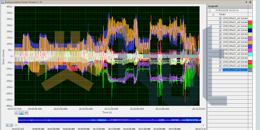
Figure 6: Results obtained during extensometry. [1]
-
- Non-destructive testing
Similarly, non-destructive testing using penetrant and ultrasonic methods was performed on the existing welds. No nonconformities were found.
Structural analysis
In view of the non-conformities found, Kot carried out a structural analysis of the bridge, with the aim of identifying points of concern in the structure and assessing possible causes. Some of the objectives of the structural assessment are listed below:
-
- Static structural analysis;
-
- Fatigue analysis;
-
- Buckling analysis;
-
- Link analysis.
Second, for the structural analysis of the overhead crane, finite element models of the structure were created using specialized software. The finite element developed for the analysis of the equipment can be seen in Figure 7 and Figure 8.
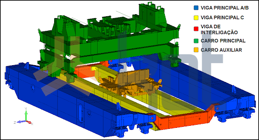
Figure 7: Finite element model of the crane. [1]
Figure 8: Finite element model of the main elevation beam. [1]
The results found during the structural simulations are summarized below:
-
- Static structural analysis:
Points were found where the utilization rate is higher than the rate allowed by the standard.
-
- Fatigue analysis:
Points were found where the utilization rate is higher than the rate allowed by the standard.
-
- Buckling analysis:
No points of non-compliance were found.
-
- Link analysis:
Points were found where the utilization rate is higher than the rate allowed by the standard.
Figure 9 shows one of the results found during the static analysis of the equipment.
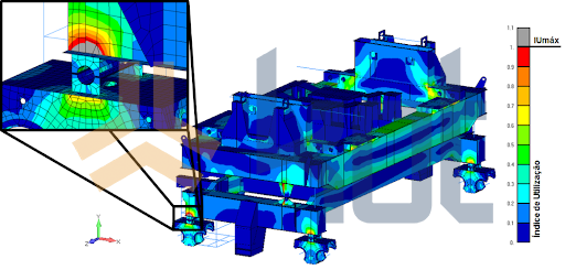
Figure 9: Utilization rates in the main car manual. [1]
The finite element model developed by Kot was validated by comparing the deformations measured during extensometry on the crane with the deformations found in the model for similar loading conditions; the results of this comparison can be seen in Figure 10.
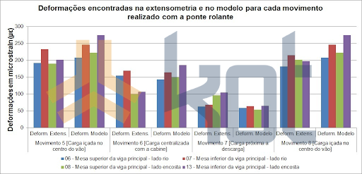
Figure 10: Deformations obtained from extensometry and the model. [1]
In fact, upon comparing the data, it was observed that the deformations present in the bridge structure are consistent with those found in the model and sufficient to ensure that the results obtained from the model are valid for the actual bridge structure. Therefore, the computational model of the bridge was considered valid.
Repowering analysis
Third, this part of the study was responsible for assessing the feasibility of repowering the bridge’s main lift mechanism to increase its capacity. To this end, it was necessary to perform a structural and mechanical evaluation of the asset, taking into account the new load requirements specified by the client company.
Finally, after conducting its analyses, Kot found no restrictions on the repowering of the overhead crane, provided that the recommended reinforcements were installed as required for the repowered condition.
Conclusion
Finally, after the analyses were completed, due to the nonconformities identified in the structural analysis of the overhead crane, proposals were presented for the changes or reinforcements needed to bring the structure into compliance with the criteria established in the standard.
In addition, fieldwork is often crucial to conducting a comprehensive study. Identifying non-conformities can prevent production downtime and even accidents. Thus, when combined with computational analyses, it is possible to gain a complete understanding of an asset’s operating context, validating computational models and uncovering information that often goes unnoticed.
Kot Engenharia has employees able to work in the field, carrying out visual inspections, non-destructive testing and data collection. Our team can also carry out various computer analyses. Contact our team for more information!
Follow our pages on LinkedIn, Facebook e Instagram to keep up with our content.


