
In general, mathematical analysis can be carried out in linear or non-linear form. In order to understand the situations in which non-linear analysis is applied, it is necessary to know the circumstances in which it is carried out. This article will present the concept of the two methods and explore the use of non-linear analysis in solving engineering problems.
Rigidity
Initially, it is necessary to understand what stiffness is and the main factors that alter it. This concept can be presented as the ability of a mechanical system to withstand the application of loads without greatly altering its shape [1]. This means that it expresses the difficulty offered to deformation in the face of a given stress.
Rigidity is directly linked to the following aspects:
- Material;
- Object format;
- Supported by.
It can be said that when the deformation of the structure does not go beyond the elastic region of the material, linear analysis is more suitable, as the properties of the materials, shapes and supports are not altered. On the other hand, when this deformity reaches the plastic range, it is necessary to apply a non-linear analysis, as at least one of these characteristics has changed.
Linear Analysis
Linear analysis is used for less complex problems. It is a simplified methodology for solving real-world problems. To do this, some mathematical and physical assumptions are usually adopted. Figure 1 shows the deformation of a braced beam.
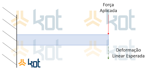
Figure 1: Deformation of a beam in linear analysis. [2]
For the linear analysis of this situation, it is assumed that the beam shown has a small linear elastic deformation in the direction of the green arrow, when it undergoes the loading represented by the red arrow. This implies that when the force is not applied, the structure will return to its initial state, unchanged. With this, the physical analysis of the object can be carried out simply and with plausible results.
Non-linear Analysis
When the system in question does not behave linearly, it is necessary to analyze it using a non-linear form. This type of model is more complex. Figure 2 shows the non-linear deformation of a braced beam.
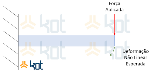
Figure 2: Deformation of a beam in nonlinear analysis. [2]
This type of analysis makes it possible to check different deformations where the system has the following characteristics, among others [3]:
- Non-linear geometry;
- Non-linear material;
- Buckling.
Linear vs. Non-Linear Analysis
The table below summarizes the predominant characteristics of each of these types of analysis [4].
| Linear Analysis | Non-linear Analysis |
| They're simpler; | They are more complex; |
| They are executed more quickly; | They give more accurate results; |
| Lower intellectual and computational costs; | Higher intellectual and computational costs; |
| There are limitations to these analyses. | They can be used in any context. |
Applications of non-linear analysis in industry
In order to make the application of the method clearer, below is a case in which Kot carried out a non-linear analysis of a Roll Over Protective Structure in the cab of an off-road truck, in accordance with ISO 3471 [5].
The vehicle was initially designed to transport materials within a mine. Subsequently, it was proposed to adapt it to perform the function of a tow truck. To do so, it was necessary to remove the truck's tipper, which made its cab more exposed to possible rollovers. Kot Engenharia therefore Kot Engenharia an analysis of the operating cab's protective structure, taking into account the vehicle's new application. Figure 3 shows the off-road vehicle without the tipper.
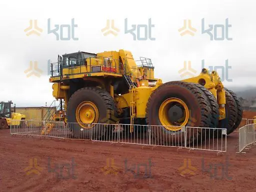
Figure 3: Off-road truck without weighbridge. [2]
According to the material data provided by the manufacturer, the need for the study to be carried out using a non-linear analysis was identified. This is justified by the fact that the material exhibits bilinear behavior, as shown in Graph 1.
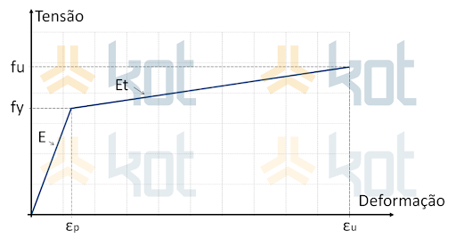
Graph 1: Stress per strain, bi-linear behavior. [2]
In which:
- fy is the yield strength;
- fu is the tensile yield strength;
- E is the modulus of elasticity;
- Et is the tangent plastic modulus, considering linear hardening;
- εp is the maximum elastic deformation;
- εu is the ultimate tensile strain.
After creating the model in finite elements, the representation was exported to LS DYNA software, where a nonlinear analysis was performed. Figure 4 shows the reproduction created for the nonlinear analysis.
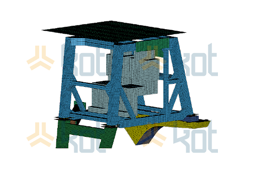
Figure 4: Finite element model converted to LS-DYNA software. [2]
After completing the analysis, reinforcements were proposed for the truck's protective structure, as the original structure was not suitable for the new conditions. Figure 5 shows the suggestions generated.
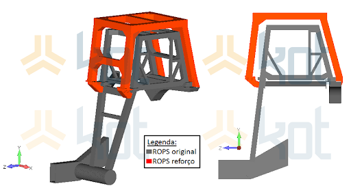
Figure 5: Proposed reinforcements. [2]
Conclusion
After reading the article, it can be concluded that nonlinear analyses are very useful in the context of engineering. Kot Engenharia the necessary knowledge to apply it, being able to evaluate different operating contexts and contribute with the results. Consult our team for more information!
Follow our pages on LinkedIn, Facebook e Instagram to keep up with our content.
References:
[1] Rogério Sales Gonçalves and João Carlos Mendes Carvalho. STUDY OF THE RIGIDITY OF MULTIBODY SYSTEMS.
[2] Kot Collection
[5] ISO-3471:2008, Earth-moving machinery - Rollover Protective Structure - Laboratory tests and performance requirements.


