
A análise mecânica de transportadores de correia é a avaliação técnica focada na verificação dimensional e operacional dos sistemas de acionamento, esticamento e roletes. O estudo determina a potência necessária em cenários comuns ou de sobrecarga, define o método de partida ideal (direta, por acoplamento hidrodinâmico ou por inversor de frequência) e valida a dissipação térmica em freios e redutores. Além disso, avalia o curso do esticamento e previne o travamento de roletes por deflexão do eixo ou desgaste de rolamentos.
Saiba como a análise mecânica otimiza a confiabilidade de transportadores de correia.
Introduction
As discussed earlier in Part 1 of this article (Mechanical Analysis of Belt Conveyors: Why Is It Important? – Part 1), belt conveyors (BCs) are equipment used for the continuous transport of materials, consisting of a continuous belt that moves over rollers and drums, contributing to transport efficiency. Furthermore, these assets are composed of various mechanical elements, such as drive and tensioning systems.
In addition to the points covered in the first part of the article, the mechanical analysis of conveyors aims to evaluate the mechanical components of the drive system and the stretching system, as well as the impact, load and return rollers. This article presents some of the checks carried out by Kot on these items.
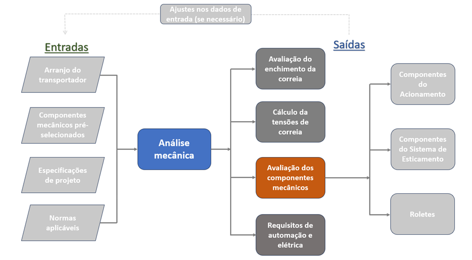
Figure 1: Summary flowchart of mechanical analysis. SOURCE: Kot Collection.
Drive system
The drive system consists of the motor, coupling, and gearbox, and may also include a flywheel, backstop, and brake. In general, in most conveyors, this system serves to provide the power necessary to drive the belt. On the other hand, in the case of conveyors with a regenerative (downhill) profile, the drive operates as a generator, controlling the belt speed and converting the mechanical energy of the movement into electrical energy.
In addition, in both scenarios, the drive system is also responsible for starting, stopping, and holding the belt in place using brakes and backstops. Figure 2 shows a schematic diagram of a conventional drive system, with its main components labeled.
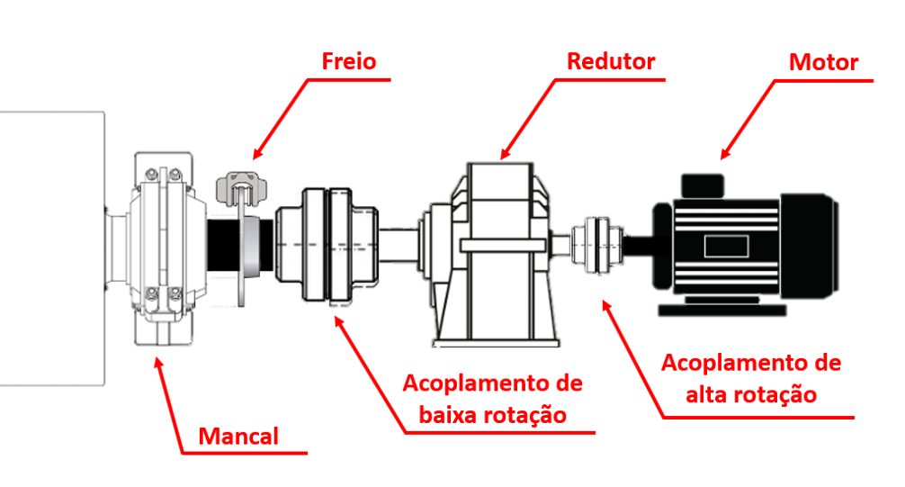
Figure 2: Example of a drive system. SOURCE: Kot Collection.
The power required by the conveyor is also calculated by specialized software used to analyze the mechanical model, as mentioned in article part 1. When sizing and evaluating the components of the drive system, it is essential to know the power required in the different operating conditions that the asset can work in, whether they are common, momentary or unusual.
Based on this, and taking into account the required power ratings, the motor utilization factors are evaluated for different operating conditions to assess the possibility of overloads, which can result in unwanted tripping or reduce the service life of the drive system components. In this regard, the calculation of overloads—whether during the design phase or for the analysis of existing conveyors—is important information that must be shared with the team responsible for analyzing the electrical system.
GIF 1 shows an example of an assessment of the power required for loading and unloading material on a long-distance belt conveyor (TCLD). In the study in question, an overload of up to 120% was identified for approximately 100 seconds during material unloading. Therefore, in this situation, this overload was reported to those responsible for sizing the electrical system so that this condition could be taken into account.
Gif 1: Evaluation of the power required for loading and unloading material. SOURCE: Kot collection.
The choice of starter type will depend on the specific needs of the conveyor, taking into account factors such as load inertia, motor power and control requirements. In addition, it is important to ensure that the type chosen meets the asset's efficiency and safety standards. The main types of starter are
-
- Direct start: The conjugate curve of the electric motor is applied (Figure 3A), which generally has a maximum value of more than 200% and a starting current six times higher than the nominal. In this case, the motor starts together with the load (Figure 3B) and, if the start is long, the motor will have a high current for a long time, which can cause breakdowns and reduce its useful life. Therefore, this type of starter is normally used for short TRs, with low power and low load inertia (short starting time).
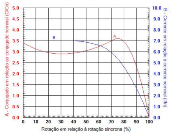
Figure 3A: Conjugation and current curve of the motor. SOURCE: WEG electronic catalog.
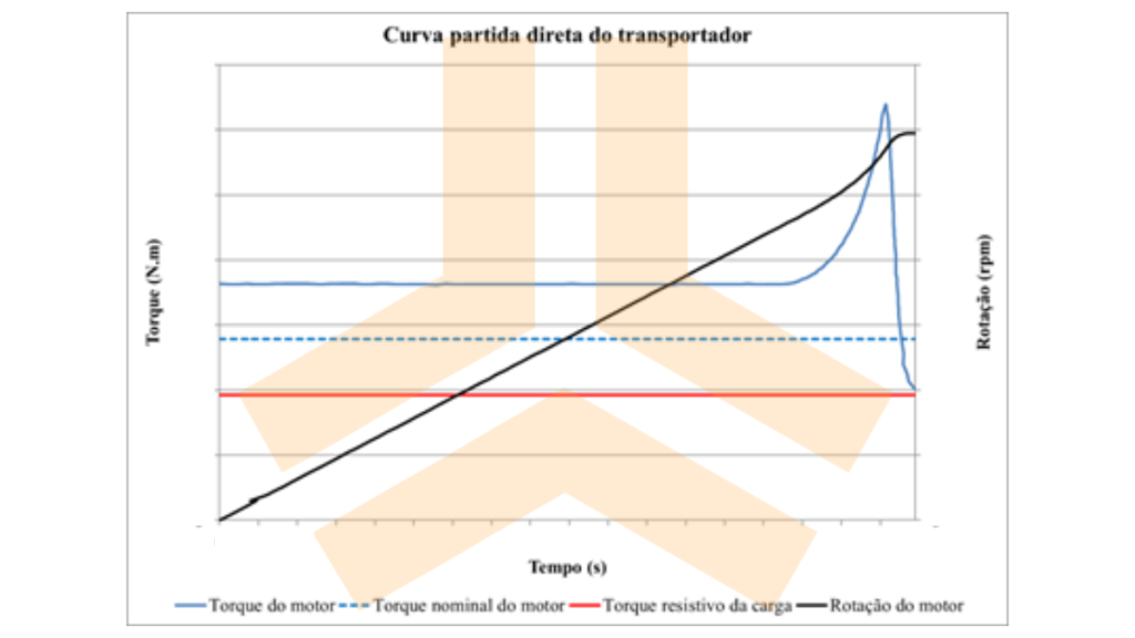
Figure 3B: Conveyor direct start curve. SOURCE: Kot Collection.
-
- By hydrodynamic coupling: The hydrodynamic coupling decouples the starts of the motor and the load, allowing the motor to do it in a short time, with a high current. The load will start after the coupling fluid starts moving and the power is transmitted between its rotors. In this way, it is possible for this event to occur with a lower overload. It is important to carry out the analysis together with the coupling manufacturer in order to assess the oil temperature during start-up, a fundamental study for the proper sizing of the coupling.
-
- By frequency inverter: The start is made on a speed curve in a pre-established time and occurs more smoothly, as illustrated in Figure 4. In frequency inverter starts, normally the maximum conjugate supplied by the motor is around 150% of the nominal.
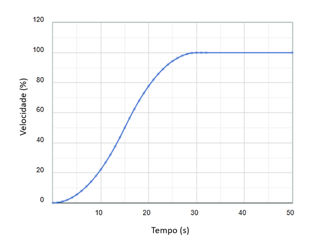
Figure 4: Frequency inverter start curve. SOURCE: https://helixconveyor.com/App/THelp/helpDynTorqueSpeed
In addition to the motor, evaluations are also carried out on the drive's other components: gearbox, couplings, brakes and backstops:
-
- Gearbox: This item is responsible for reducing the speed of the motor, and mechanical and thermal capacity assessments are carried out. This mechanical analysis relates to the mechanical strength of the gearbox components, while the thermal study involves heat dissipation. If the gearbox is not sized correctly or there is an overload in the drive system, the oil temperature can exceed the maximum permissible. As a result, the viscosity of the oil may decrease, compromising lubrication and creating a scenario conducive to excessive wear of the gear teeth.
-
- Coupling and backstop: Couplings transmit power between components. The backstop is responsible for preventing the reversal of the belt's direction of rotation, preventing material from returning during idle moments on the conveyor, especially on ascending conveyors, which are more prone to backstopping. The study of these items is carried out in accordance with their manufacturer's definitions, in order to validate their operation and consolidate operational safety.
Figure 5 shows an example of a double drive configuration with backstops on both sides of the drive.
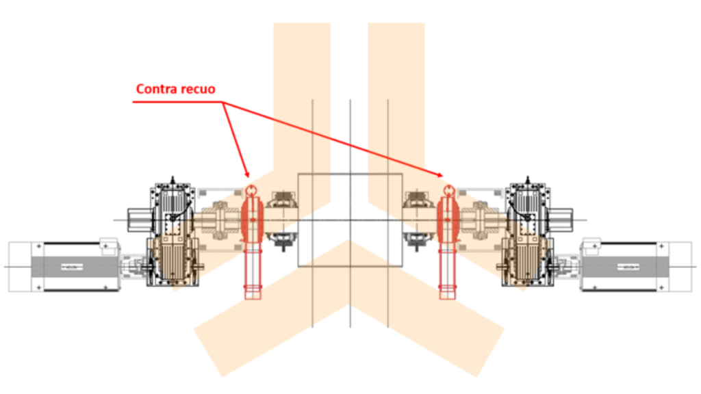
Figure 5: Double drive system with counter recoil on both sides. SOURCE: Kot Collection.
-
- Brakes: The emergency braking time is evaluated, either statically or dynamically, and the safety factor of the braking torque. Predicting the behavior of the belt and the tensions acting in this condition is fundamental for sizing the conveyor. In addition, it should be noted that dynamic analyses of stops, emergency or otherwise, often identify the need to include a flywheel to soften the dynamic behavior of the belt and control the maximum and minimum stress levels.
In addition to the assessments mentioned for the brakes, thermal analyses are also carried out considering the energy to be dissipated during braking. High brake caliper temperatures can reduce their coefficient of friction with the disc. Therefore, for safe brake operation, it is essential that the necessary heat dissipation is taken into account when sizing the disc and caliper.
Stretching system
Every conveyor has a belt tensioning system, which aims to adjust the tension of the belt along its entire length. Its proper operation is able to prevent non-conformities such as excessive deflection, compression and belt slippage, which impair or make it impossible for the equipment to function. Stretching can be fixed center (screw or hydraulic cylinders), counterweight or winch (electromechanical or hydraulic). Fixed center stretching is normally used for short conveyors, while counterweight and winch stretching is more commonly used for larger TRs. Figure 6 shows a schematic drawing of vertical gravity stretching.
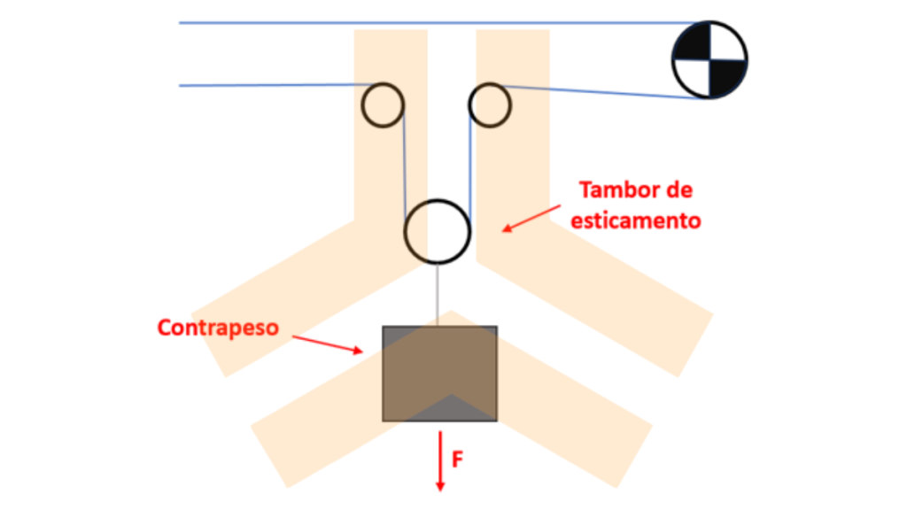
Figure 6: Vertical gravity stretching. SOURCE: Kot Collection.
For example, in the case of vertical or horizontal gravity hoisting, the main checks performed concern the safety factors of the steel wire rope and the minimum diameter of the system’s pulleys and sheaves. For hoisting using electric or hydraulic winches, the main analyses focus on the required power and the winch’s braking torque, in addition to the studies conducted for gravity systems.
Finally, the conveyor's stretching stroke is checked according to the belt model, the stretching force, the conveyor's belt tensions in a transient regime and the asset's maintenance needs. An inadequate stroke can cause operational problems, such as collision with the structure and loss of stretching force, as well as hindering maintenance on the conveyor.
Rollers
Rollers are responsible for guiding the belt along the entire conveyor and can be impact, load, or return rollers. Roller breakage and frequent jamming can significantly impair the equipment’s operational availability. In this regard, proper sizing is essential for the asset’s efficiency. Furthermore, it should also be noted that the jamming of these components increases the risk of fire.
In short, the service life of the bearings, the shaft deflection in the region of these bearings and the maximum permissible rotation are evaluated, following the recommendations of the applicable standards. Studying the service life of these components and the maximum permissible rotation are important to avoid constant and premature failure of the rollers. On the other hand, the analysis of shaft deflection in the bearing area is important to prevent the rollers from locking. Figure 7 shows the deflection of this shaft schematically.
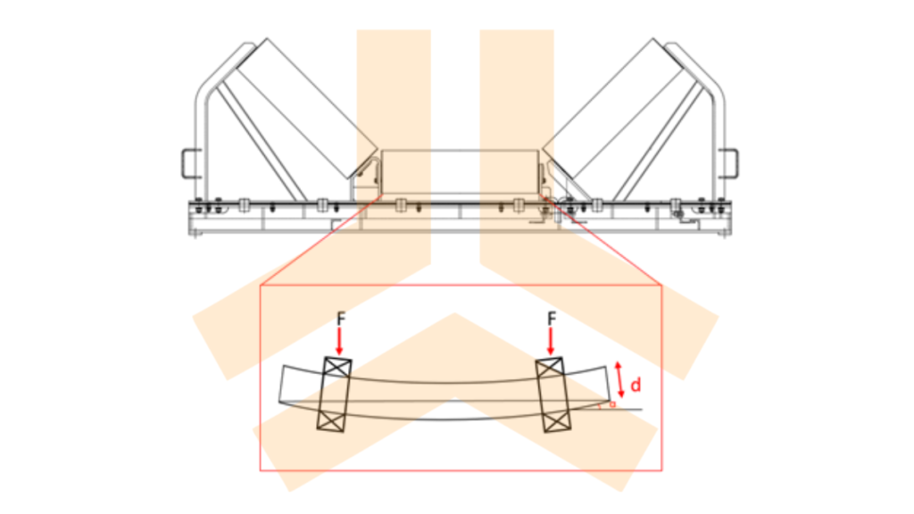
Figure 7: Deflection of the roller shaft. SOURCE: Kot collection.
Conclusion
In summary, evaluations of the mechanical components of drive systems aim to assess the selection and sizing of the motor, gearbox, couplings, brakes, and backstops. Undersizing these components can lead to a reduced service life, unscheduled maintenance, and even accidents involving the equipment.
Similarly, just as with the drive system, proper sizing of the tensioning system is also essential for the proper functioning and operational safety of conveyors. In addition, rollers are also crucial components for ensuring that the equipment maintains high availability.
Given this, it is clear that a comprehensive analysis of belt conveyors is of the utmost importance, both for new projects and for existing conveyors, whether for system sizing or for identifying and mitigating problems that arise in the field. Therefore, investing in the mechanical analysis of belt conveyors is crucial for ensuring more efficient operation.
Kot has a team of qualified Structural Integrity professionals ready to develop the best engineering solutions for your business. Contact our experts for more information!
Follow our pages on LinkedIn, Facebook e Instagram to keep up with our content.
FAQ
1. Como o tipo de partida do motor afeta a vida útil e a operação de um transportador de correia?
A escolha do método de partida determina os níveis de corrente, conjugado e tensão aplicados ao motor e à correia:
-
Partida Direta: O motor parte simultaneamente com a carga. Apresenta picos de corrente até seis vezes superiores à nominal e conjugado máximo elevado. É indicada apenas para transportadores curtos e de baixa inércia, pois partidas longas sob alta corrente provocam desarmes e reduzem a vida útil dos equipamentos.
-
Acoplamento Hidrodinâmico: Desacopla a partida do motor da partida da carga. O motor atinge a rotação rapidamente e a potência é transmitida suavemente pelo fluido do acoplamento, reduzindo a sobrecarga inicial.
-
Inversor de Frequência: Promove a aceleração em uma curva de velocidade suave e preestabelecida, mantendo o conjugado máximo controlado em cerca de 150% do nominal, reduzindo o estresse mecânico na correia.
2. Quais são as verificações térmicas e mecânicas indispensáveis nos redutores e freios?
-
Redutores de Velocidade: Além da resistência mecânica dos componentes, a capacidade térmica deve ser avaliada. Se a dissipação de calor for insuficiente ou houver sobrecarga contínua, a elevação de temperatura do óleo reduz sua viscosidade, comprometendo a lubrificação e provocando o desgaste prematuro dos dentes das engrenagens.
-
Sistemas de Freio: Exigem análises térmicas para calcular a energia a ser dissipada nas paradas de emergência. O superaquecimento do disco e das pinças reduz o coeficiente de atrito, podendo causar falhas na frenagem. Em muitos casos, utiliza-se um volante de inércia para suavizar o comportamento dinâmico e controlar picos de tensão.
3. Qual é a importância de calcular corretamente o curso e os componentes do sistema de esticamento?
O sistema de esticamento (seja por gravidade, guincho ou parafuso) mantém a tensão da correia adequada ao longo de todo o percurso, evitando problemas como flecha excessiva, compressão ou escorregamento na tambor de acionamento. A verificação inclui:
-
Fatores de segurança do cabo de aço e diâmetros mínimos de polias/roldanas;
-
Análise da potência e torque de frenagem em guinchos eletromecânicos/hidráulicos;
-
Dimensionamento correto do curso de esticamento, prevenindo a perda de força de esticamento, colisões contra a estrutura do transportador ou dificuldades durante intervenções de manutenção.
4. O que causa a quebra e o travamento prematuro dos roletes de carga, impacto e retorno?
Os roletes podem falhar devido a três fatores críticos avaliados na análise mecânica:
-
Deflexão excessiva do eixo: Ocorrem deformações no eixo que ultrapassam os limites suportados pelos rolamentos, travando o giro do rolo e aumentando o atrito contra a correia (o que pode gerar risco de incêndio);
-
Excesso de rotação: Operar acima da rotação máxima admissível acelera o desgaste mecânico do componente;
-
Subdimensionamento da vida útil dos rolamentos: Seleção inadequada da capacidade de carga em relação às solicitações reais de operação.


