")
A análise mecânica de transportadores de correia é um estudo fundamental para avaliar o desempenho, a segurança e a confiabilidade de novos projetos, repotenciamentos e ativos existentes. Por meio da verificação do grau de enchimento da correia, do cálculo de tensões em regime permanente e transiente e do desenvolvimento de análises dinâmicas, a metodologia permite diagnosticar riscos como transbordamento de material, tensões compressivas em frenagens, escorregamento em tambores e o fenômeno de flapping.
Entenda como a análise mecânica previne falhas em transportadores de correia.
Introduction
Belt conveyors (BCs) are conveying systems composed of various mechanical components and are widely used in diverse industrial sectors for handling bulk or unitized materials. As a continuous conveying system, the belt conveyor can be used for both short and long distances, ensuring efficient handling of these materials.
In addition, the mechanical systems and components that make up belt conveyors include:
Drive: responsible for the driving force, including motors, couplings, speed reducers and brakes.
Belt: this is the component that is in direct contact with the material being transported, made of flexible and resistant materials such as rubber and steel.
Rollers: these are rollers that support and direct the belt. There are different types, such as load, return, impact and transition rollers.
Drums: these are responsible for transmitting power, returning and deflecting the belt, and can be discharge, return, stretching, drive, deflection, stop or turning.
Tensioning system: this is the system responsible for maintaining the right tension on the belt.
In summary, mechanical analysis is the study used to evaluate the performance, reliability, and safety of a conveyor’s mechanical components and support structures in light of the forces acting on the equipment. Thus, this evaluation is essential for the correct sizing and operation of the conveyor system, thereby mitigating failures, damage, and accidents, and can be performed both for the design of new conveyors and for the diagnosis of existing conveyors. Figure 1 presents a flowchart of this analysis.

Figure 1: Flowchart of the mechanical analysis of belt conveyors.
Figure 2 shows a general layout of an inclined belt conveyor. Similarly, Figure 3 shows a simplified layout of the same conveyor, which was used to develop the mechanical analysis models.
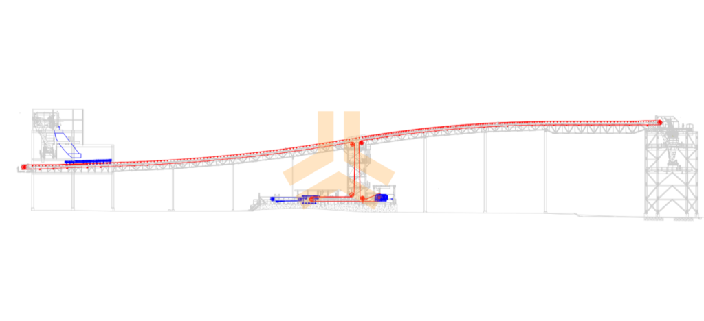
Figure 2: General arrangement of a belt conveyor.
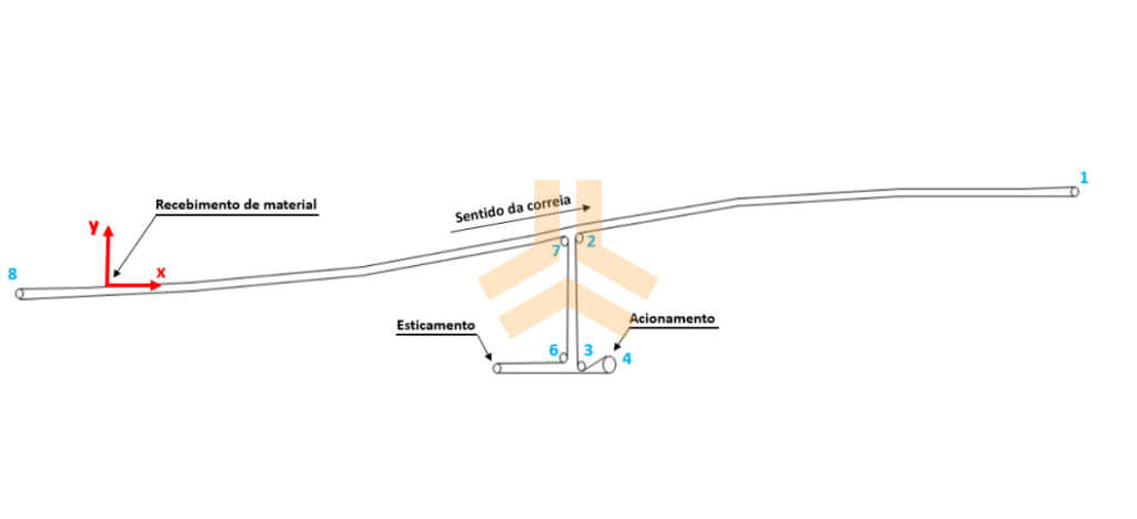
Figure 3: Simplified model of a conveyor used in the mechanical analysis.
Furthermore, mechanical analysis can also be essential for repowering and retrofitting projects, in which mechanical systems and components are inspected to assess the impact of changes on the conveyor.Additionally, for existing conveyors that are not in compliance, mechanical analysis helps not only to diagnose the problem but also to propose solutions to mitigate it.
In general, the steps involved in the mechanical analysis of a conveyor depend on the characteristics of the equipment and the purpose of the inspection (design, repowering, retrofitting, and/or fault identification). The main assessments performed, which will be detailed in this first part of the article, are: belt tension assessment and calculation of belt stresses. See Part 2 of this article for details on how inspections of other mechanical components, such as the motor, gearbox, and couplings, are performed.
Evaluation of belt filling
First, the belt fill analysis aims to assess the risk of material spillage and blockage. As outlined in a standard, the fill ratio is calculated as the ratio of the material area to the available area defined by the belt conveyor’s geometry, both in the cross-section. GIF 1 shows examples of a belt fill assessment for the transport of a material with a larger particle size and another with a smaller particle size.
Gif 1: Evaluation of belt filling (larger and smaller grain sizes).
In repowering projects to increase conveying capacity and in situations where materials with a lower density need to be handled, for example, the assessment of belt filling is essential to verify the need to increase conveyor speed.
Calculating belt tensions
Second, belt tension calculations are performed using specialized software that evaluates the conveyor’s behavior under steady-state and transient conditions (startup and shutdown). For belt tension calculations, the methodology presented in an international standard is typically used, in which resistances are divided into primary resistances (belt friction resistance on the rollers and lifting resistance) and secondary resistances (friction of the drums, scrapers, and material acceleration during feeding, for example).
In this regard, the frictional resistance between the belt and the rollers is often a significant factor, especially for long conveyors. The friction factor depends on the equipment’s operating conditions, such as duration of use and weather conditions. For new conveyors and lower ambient temperatures, higher friction resistance is expected (High Friction). Conversely, for older conveyors and higher ambient temperatures, lower friction resistance is expected (Low Friction).
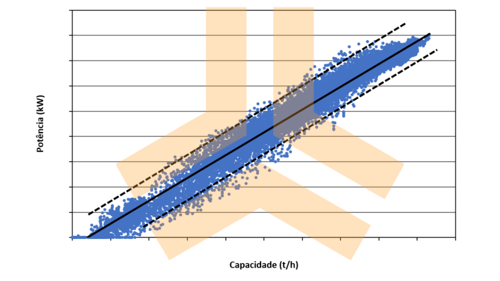
Figure 4: Example of the graph of power required as a function of transport capacity used to calibrate the mechanical model.
Calibrating the model is important in order to carry out mechanical calculations that are closer to real conditions for existing conveyors, but it is not an impediment to carrying out the mechanical analysis. In the case of designing new conveyors, as well as evaluating existing conveyors that do not have field data available, the friction factor can be calculated as proposed in an international standard.
Dynamic analysis
Static analyses are carried out using analytical calculations and do not take into account dynamic effects due to the elasticity and damping of the belt. Thus, especially for larger conveyors, static evaluations, although they do a good job of assessing permanent regimes, are not enough to adequately study the conveyor's transient conditions. Dynamic analyses are therefore necessary for checking these regimes (start and stop). Gif 2 shows an example of the dynamic assessment carried out for the emergency braking of an ore conveyor at the design stage. In the initial conditions, the brake was located on the discharge drum, together with the drive. In the analysis of the emergency braking condition with material, compressive belt stresses were identified in the loading region, which can cause belt damage, material spillage and belt misalignment, for example.
It was therefore proposed to relocate the brake to the return drum (#7). It is clear from the comparison shown in Gif 2 that with the proposed configuration compressive stresses do not occur, thus avoiding the undesired conditions.
Gif 2: Belt tensions during emergency braking (initial configuration and proposed configuration).
The minimum stresses are evaluated for both the permanent and transient regimes. In both cases, the maximum deflections in the belt are evaluated.
After calculating the belt tensions in the permanent and transient regimes, in addition to evaluating the minimum tensions, the following evaluations are carried out:
-
- Evaluation of the belt (overall strength, maximum and minimum local stresses, drum slippage, minimum drum diameter and flapping);
-
- Drum evaluation;
-
- Evaluation of the structures in the drum regions.
Belt assessment
-
- Maximum belt tensions (overall assessment)
Based on the belt tensions calculated for the permanent regime and the transient regime, checks are made on the utilization rate of the belt, comparing the maximum acting tensions with the admissible tension given in the manufacturer's catalog. Figure 5 shows an example of a check carried out for a conveyor where the belt tension in the permanent regime for the design capacity is higher than the maximum permissible tension.
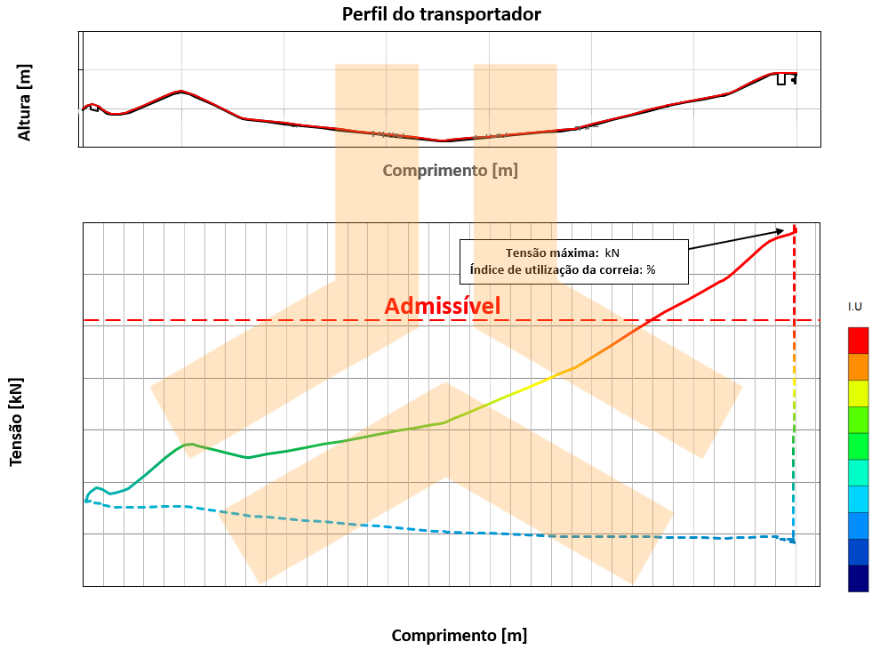
Figure 5: Belt tensions along the conveyor in permanent regime for design capacity.
-
- Local belt tensions (maximum and minimum)
In addition to the study of global belt stresses, the mechanical analysis of this type of asset also involves the assessment of local stresses at the return and discharge transition distances, at the concave and convex curves and at the belt turns. In these areas, the belt stresses are redistributed along the belt profile, and can increase at the edges and decrease in the center, or vice versa. Analysis of this distribution is essential for determining the minimum transition distances, minimum curve radii and minimum lengths of the belt turners. In the case of concave curves, the lifting condition of the belt is also calculated.
Gif 3 shows an example of evaluating the local stresses in a turner. You can see the increase in stresses at the edges and the decrease in stresses at the center of the belt in this case.
Gif 3: Analysis of local belt stresses in a turner.
In addition to evaluating the maximum and minimum stresses acting on the conveyor, the drive drum is also analyzed for belt slippage, minimum drum diameters and belt flapping.
Slipping: In order for the torque of the drive drum to be transmitted to the belt, a minimum tension, defined in the standards, must be applied. If this tension is lower than the minimum permissible, the belt may slip on the drive drum, compromising the transmission of drive power and causing wear to the belt and drum lining.
Minimum drum diameter: The minimum diameter of the drums is defined by the belt manufacturer and by an international standard, depending on the model and the rate of use of the belt in the region of the drums. Drum diameters smaller than recommended can lead to a reduction in the service life of the belt carcass.
Beltflapping: Flapping is a phenomenon that causes excessive vibration of the belt in the return region and can result in increased wear of the belt and reduced service life of the rollers. The phenomenon occurs when the belt is excited by the frequency of rotation of the rollers, with a coupling of the natural and excitation frequencies.
Analysis of drums and support structures
The belt tensions obtained in the mechanical analysis are used as input data for the calculations of the drums and support structures, as shown schematically in Gif 4.
Gif 4: Application of belt tension in the analysis of drums and conveyor structures.
A detailed article on drum analysis is available on the Kot Blog: Drums on belt conveyors: What they are and why they matter.
Conclusion
The mechanical analysis of belt conveyors is fundamental both for the design of new conveyors and for the evaluation of existing conveyors. By identifying and correcting non-conformities, it is possible to avoid future unplanned downtime, mitigate the risk of accidents and reduce maintenance costs. Investing in the mechanical analysis of belt conveyors is essential for their operation to be efficient and sustainable, contributing to the overall success of operations.
Kot has a team of qualified Structural Integrity professionals ready to develop the best engineering solutions for your business. Contact our experts for more information!
Follow our pages on LinkedIn, Facebook e Instagram to keep up with our content.
FAQ
1. O que é a análise mecânica de transportadores de correia e quando ela deve ser aplicada?
-
A análise mecânica é o estudo das forças atuantes sobre os componentes e estruturas de suporte de um transportador, visando garantir seu correto dimensionamento, desempenho e segurança.
-
Ela é aplicada na fase de projeto de novos equipamentos, em estudos de repotenciamento (aumento de capacidade ou alteração do material transportado) e no diagnóstico de falhas de ativos em operação.
2. Como é calculada a taxa de enchimento da correia e qual a sua importância?
-
O grau de enchimento é obtido pela razão entre a área da seção transversal ocupada pelo material e a área total disponível pela geometria do transportador.
-
Essa medição evita o transbordamento de carga e a queda de blocos maiores (matacos).
-
É uma avaliação indispensável em projetos de repotenciamento ou ao alterar a densidade e a granulometria do material transportado.
3. Por que as análises dinâmicas são necessárias além das análises estáticas?
-
As análises estáticas calculam as resistências em regime permanente, mas não consideram os efeitos de elasticidade e amortecimento da correia.
-
Em transportadores de grande porte, as análises dinâmicas são indispensáveis para simular regimes transientes (partida, parada e frenagem de emergência).
-
Elas identificam cenários críticos, como o aparecimento de tensões compressivas que causam derramamento de material, desalinhamento e danos à estrutura da correia.
4. Quais avaliações locais de tensão de correia devem ser realizadas?
-
Além da verificação global de resistência da correia, analisa-se a distribuição local de tensões em regiões de transição, curvas côncavas/convexas e viradores.
-
Nessas regiões, as tensões se redistribuem entre as bordas e o centro da peça.
-
Nas curvas côncavas, o cálculo é crucial para prever e evitar o levantamento da correia (lift-off).
5. Quais falhas operacionais na correia e nos tambores a análise mecânica previne?
-
Escorregamento no tambor: Verifica se a tensão mínima no tambor de acionamento é suficiente para transmitir torque sem desgastar o revestimento e a correia.
-
Diâmetro insuficiente do tambor: Garante que os diâmetros dos tambores respeitem as especificações dos fabricantes, evitando fadiga prematura na carcaça da correia.
-
Fenômeno de Flapping: Previne vibrações ressonantes na região de retorno causadas pelo acoplamento entre a frequência da correia e a rotação dos roletes.


