
Introduction
Currently, in various industrial settings, interactions between a solid object and a flowing fluid can be observed. In this regard, when the focus of the study is the flowing fluid, the technique of computationalfluid dynamics (CFD) can be applied. If you are interested in this subject, check out the links below for some of the posts on the Kot Blog on this topic:
The Federal Remediation Technologies Roundtable ( FRTR) defines the dredging process as the removal, treatment, and/or relocation of submerged contaminated sediments or contaminants [1]. Similarly, this definition aligns with the description of the environmental remediation dredging process outlined by the Brazilian Navy’s Ports and Coasts Directorate, which defines it as “The act of removing material and sediments from the bed of water bodies for a specific purpose […] carried out to improve environmental or sanitary conditions.” [2]. This type of dredging is performed to reduce the risks of the materials posing any kind of threat to human health or the environment.
The equipment used for dredging is known as dredgers and is commonly classified as mechanical dredgers, hydraulic dredgers, or pneumatic dredgers. In addition, hybrid models of these machines are also available. In short, their operation can be described as [1]:
-
- Mechanical dredgers: equipment that dredges using mechanical devices, such as excavators;
-
- Hydraulic dredgers: equipment that dredges using the addition of water to form a fluid with the material to be removed, which can be pumped through pipes;
-
- Pneumatic dredgers: equipment that dredges using air pumping to suck up material with a small amount of water;
-
- Hybrid dredges: an arrangement of equipment that uses mechanical and hydraulic components to remove material.
Figure 1 shows a schematic of the dredging, dewatering and water treatment process.
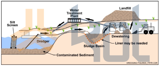
Figure 1: Example of dredging, dewatering and water treatment. [1]
Kot conducted a study analyzing the drag forces on the floats of a dredge’s feed pipe using CFD analysis. These dredges are responsible for removing tailings from the reservoir that result from the bauxite ore washing process. Subsequently, these tailings are transported through a pipe to the reservoir wall. This pipe, in turn, is dragged by the dredger, which, upon contact with the fluid, generates a drag force opposite to the movement of the vessels.
Objective
The main objective of the study was to evaluate the drag force exerted by the movement of the dredgers, in order to determine the appropriate sizing of the steel cable and the anchor heads.
Development
First, at the start of the analysis, the model was created, and the boundary conditions—such as water flow perpendicular to the pipe—were defined and applied. Figures 2 and 3 show the computational model generated for the study and the mesh used in the model, respectively.
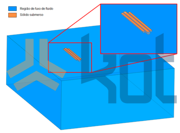
Figure 2: Model used in CFD analysis. [3]
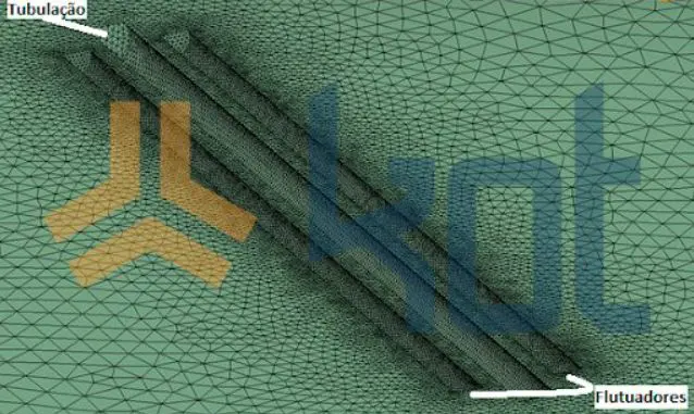
Figure 3: Final mesh of the CFD model. [3]
Some of the results obtained from the calculations and analyses carried out can be seen in Figures 4 to 7.
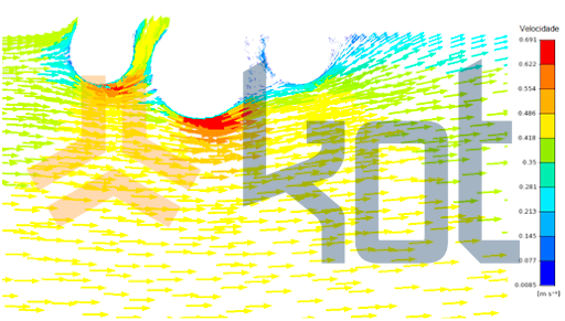
Figure 4: Velocity profiles around the pipe [m/s] [3].
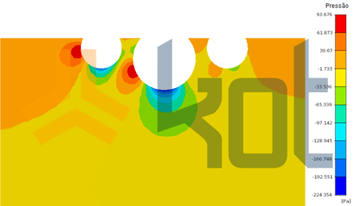
Figure 5: Pressure distribution [Pa]. [3]
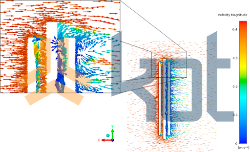
Figure 6: Velocity vectors around the pipe - Top view. [3]
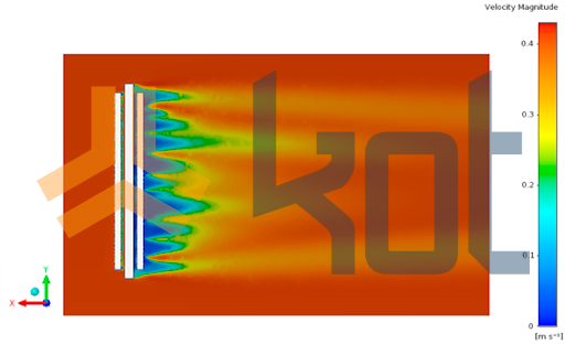
Figure 7: Velocity profile around the pipe - Top view. [3]
Finally, the study’s objective was achieved using the drag force equation. Thus, the computational analyses and analytical calculations to determine the maximum drag force acting on the pipes and dredgers showed that the drag coefficients are very high for this application, which influences the dredger’s movement trajectory, as shown in Figure 8.
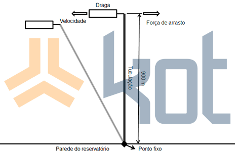
Figure 8: Schematic view of dredge movement. [3]
In conclusion, CFD analyses have a wide range of applications in an industrial context, not only under design conditions but also for evaluating real-world scenarios in existing systems. These studies enable a physical-mathematical understanding of complex events and/or those not visible to the naked eye.
Kot has experience in this area and can help you with your company's needs. Contact our team for more information!
Follow our pages on LinkedIn, Facebook e Instagram to keep up with our content.
FAQ
1. O que é a dragagem de recuperação ambiental e qual a sua finalidade segundo o texto?
É o processo de remoção, tratamento e/ou realocação de sedimentos e materiais contaminados presentes no leito de corpos d’água. Sua finalidade específica é melhorar as condições ambientais ou sanitárias, reduzindo as ameaças que esses materiais representam para o meio ambiente e para a saúde humana.
2. Quais são os tipos de dragas apresentados no artigo e como elas funcionam?
O texto classifica as dragas em quatro categorias principais:
-
Dragas mecânicas: Realizam a retirada de material por meio de dispositivos mecânicos (como escavadeiras);
-
Dragas hidráulicas: Adicionam água ao material para formar uma polpa bombeável por tubulações;
-
Dragas pneumáticas: Utilizam o bombeamento de ar para realizar a sucção do material com uma pequena quantidade de água;
-
Dragas híbridas: Utilizam um arranjo combinado de componentes mecânicos e hidráulicos.
3. Qual era o cenário operacional e o objetivo principal do estudo de CFD?
O cenário envolvia dragas operando na retirada de rejeitos resultantes da lavagem de minério de bauxita em um reservatório. Esses rejeitos eram transportados até a parede do reservatório por uma tubulação flutuante que era arrastada pela própria draga.
O objetivo principal do estudo foi avaliar a força de arrasto gerada pelo contato da tubulação com a água durante o movimento, permitindo dimensionar adequadamente o cabo de aço e os cabeços de ancoragem do sistema.
4. Quais condições de contorno foram aplicadas na modelagem computacional em CFD?
Foi elaborado um modelo tridimensional da tubulação e gerada uma malha computacional para os cálculos. Como condição de contorno fundamental para a análise, definiu-se o fluxo de água atuando de forma perpendicular à tubulação flutuante.
5. Quais resultados gráficos foram extraídos da simulação em CFD?
A análise computacional permitiu mapear e visualizar:
-
Perfis de velocidade da água em torno da tubulação (em m/s);
-
Distribuição de pressão na superfície e no entorno (em Pa);
-
Vetores e perfis de velocidade em vista superior ao redor do tubo.
6. O que o estudo concluiu sobre as forças de arrasto e o movimento da draga?
A integração entre as análises computacionais e os cálculos analíticos da equação da força de arrasto determinou a carga máxima atuante na tubulação e na embarcação. Concluiu-se que os coeficientes de arrasto eram muito elevados para a aplicação, o que gerava impacto direto e alterava a trajetória de movimentação da draga durante a operação.
7. Qual a importância da aplicação da análise CFD em sistemas existentes segundo o artigo?
O artigo destaca que a técnica de CFD possui ampla aplicabilidade não apenas na fase de projeto, mas também na avaliação de cenários operacionais reais. A ferramenta permite a compreensão físico-matemática de eventos fluidodinâmicos complexos ou não visíveis a olho nu, garantindo a tomada de decisões assertivas para a segurança e dimensionamento de ativos industriais.
References:
[1] https://frtr.gov/matrix/Environmental-Dredging/#Introduction
[2] RULES OF THE MARITIME AUTHORITY FOR WORKS, DREDGING, RESEARCH AND MINING OF MINERALS UNDER, OVER AND ON THE SHORES OF BRAZILIAN JURISDICTIONAL WATERS
[3] Kot Collection