Introduction
Frequency inverters are devices used in drive systems to control the torque and speed of alternating current motors by controlling the magnitude and frequency of the supply voltage. In order to obtain an alternating voltage with the desired characteristics, inverters work by converting the mains voltage into direct voltage and then converting it back into alternating voltage, controlling the parameters of this second conversion, as illustrated in Figure 1.

Figure 1: Voltage conversion in an inverter (Source: adapted from Citisystems)
The output alternating voltage is generated from direct voltage pulses, and by varying the frequency, width and signal of these pulses, the amplitude and frequency of the output alternating voltage also change, as can be seen in Figure 2. This technique is called pulse width modulation, and is better known by its acronym PWM.

Figure 2: PWM modulation of a frequency inverter (Source: adapted from Citisystems)
One problem that can be caused by this feature of inverter operation is the excitation of torsional vibration modes of the motor shaft and/or the structure in which it is located. This is because these pulsations in the motor drive voltage can cause pulsations in the motor torque, which in turn can resonate with the structure.
This article deals with one of Kot's success stories, in which an investigative analysis of the vibration of the platform of a shoe feeder system was carried out. The platform in question supports two feeders, see Figure 3, whose drive motors are controlled by frequency inverters, and showed vibration of the floor, the base of the motors, and frequent failure of the elastic elements of the couplings.

Figura 3: Plataforma dos alimentadores. (Fonte: acervo Kot Engenharia)
In order to determine the cause of the vibration, Kot carried out visual inspections, measurements and computer analysis using the Finite Element Method (FEM).
Execution of the service
The activities began with a visit to the equipment, during which a visual inspection was carried out, as well as measurements with a motion amplification camera and accelerometry at points of interest on the structure. The main objective of this stage was to gather data to formulate hypotheses.
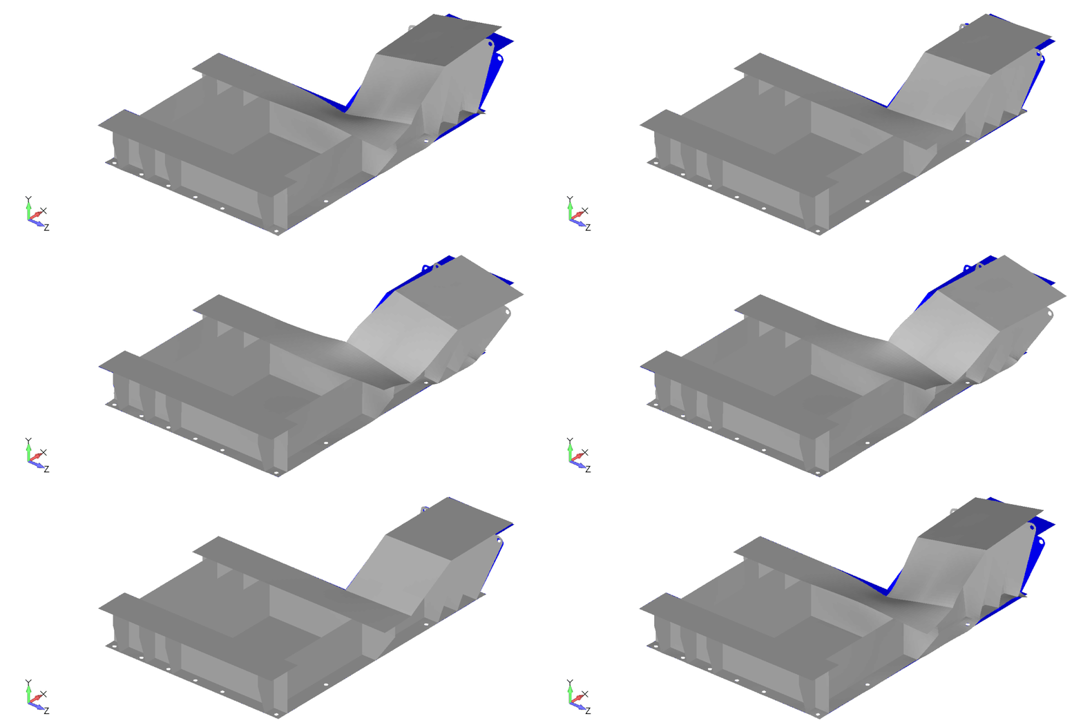
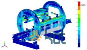
Once hypotheses about the cause of the vibration had been established, computer simulations of the structure were carried out to see if the proposed cause would be capable of producing dynamic behavior similar to that observed. To do this, two different models were developed: a local model of the base of the drives and a global model of the platform, see figure 4. The local model was used to carry out a more detailed transient modal and dynamic analysis of the base of the drive, in order to quantify the magnitude of the excitation associated with the vibrations measured. The global model, due to the simplifications inherent in the beam elements and the rigidity of their connections, was used to understand and evaluate the general behavior of the structure when subjected to the loads calibrated by the detailed model.

Figura 4: Modelos. (Fonte: acervo Kot Engenharia)
Finally, once there was consistency between the hypothesis raised and the results of the simulations, an intervention was carried out on the equipment, followed by new measurements, to assess the effectiveness of the proposed modifications.
Resultados
During the inspection, it was observed that the platform only showed noticeable vibration when the level of material in the system was above a certain threshold, and when the motors were operating at a specific rotational frequency. In addition, it was noted that the failure aspect of the motor couplings was characteristic of torsional vibration.
The measurements showed that the vertical response at the base of the motor is similar in magnitude to the horizontal response, and that both are more pronounced than the longitudinal response, as shown in graph 1. This behavior can be caused by radial or torsional vibration of the motor, however, given the failure aspect of the couplings, the second option was credited.

Gráfico 1: Vibração medida na base do motor. (Fonte: acervo Kot Engenharia)
It was also noted that both the platform and the base of the motors vibrated at the same frequency, as shown in graph 2, which was much higher than the motors' rotation frequency. This pronounced response is not associated with any behavior typical of mechanical problems with the equipment in question, given its constructive characteristics. Video 1 shows footage of the platform vibrating, taken using a camera with motion amplification.

Gráfico 2: Comparação entre medições na plataforma e na base do motor – Velocidade vertical. (Fonte: acervo Kot Engenharia),
Vídeo 1: Filmagem da plataforma vibrando – Câmera com amplificação de movimento. (Fonte: acervo Kot Engenharia)
Based on the characteristics highlighted, it was hypothesized that the cause of the vibration would be a pulsation in the torque of the motors, caused by the speed modulation by the frequency inverter.
The modal analysis of the base of the drives showed that the torsional natural frequency of this structure coincides with the measured vibration frequency. The associated vibration mode is shown in video 2. Furthermore, in the transient dynamic analysis, it was shown that a pulsation of the drive torque, oscillating at this frequency and with a magnitude lower than the motor's nominal torque, would be capable of causing a vibration in the structure with intensity and characteristics similar to those observed in the measurements. Graph 3 shows a comparison between the vibration measurements on the motor base and the results obtained by the model.

Vídeo 2: Modo de vibração torcional da base do motor. (Fonte: acervo Kot Engenharia)

Gráfico 3: Comparação entre medição e modelo – Velocidades na base do motor. (Fonte: acervo Kot Engenharia)
The results of the frequency response analysis showed that, when excited by a pulse in the drive torque at a frequency of approximately 4 times the motor speed, the platform's dynamic response has characteristics similar to those observed in the measurements, as shown in graph 4.

Gráfico 4: Comparação entre medição e modelo – Velocidades na plataforma. (Fonte: acervo Kot Engenharia)
Given that the results of the computer analysis supported the hypothesis raised by Kot, an intervention was carried out on the equipment, in which the frequency inverter's operating parameters were adjusted by the manufacturer. After the intervention, the vibration intensities measured on the platform and at the bases of the drives, which had previously been higher than the normative admissible limits, were significantly reduced and became lower than the normative limits. In addition, the responses began to occur at the motor's rotation frequency and at its second harmonic, which is an expected behavior for the equipment. Graph 5 shows a comparison of the horizontal vibration measured at the base of the motor before and after the intervention, showing the change in response frequencies and the reduction in magnitude, which in this case was 92%.

Gráfico 5: Comparação entre antes e depois da intervenção – Velocidade horizontal na base do motor. (Fonte: acervo Kot Engenharia)
Conclusion
Frequency inverters are a point of attention in vibration problems, and it is important to discern when the characteristics of the vibration point to mechanical or electrical causes.
Through vibration measurements, as well as visual inspection, it was possible to adequately characterize the vibration of the structure, making it possible to identify the inverter as the main cause of the problem, which highlights the importance of correct instrumentation of structures and a well-executed data survey.
Finally, computer analysis proved to be an important tool in validating the hypothesis raised, ensuring greater certainty as to the effectiveness of the proposed intervention, thus helping to minimize losses and rework in the field.
If you, like our more than 150 clients, are looking for engineering solutions for your operation, contact our team and find out more about our services. Since 1993, we have specialized in developing engineering solutions using computational methods.
Follow our pages on LinkedIn, Facebook e Instagram to keep up with our content.


