
Quando um novo virador de vagões fabricado com base em um projeto antigo começou a apresentar trincas estruturais prematuras e sobrecarga crônica no sistema de acionamento, um diagnóstico de engenharia avançado foi necessário para evitar o colapso operacional do ativo. A Kot Engenharia desenvolveu um modelo computacional completo utilizando o Método dos Elementos Finitos (MEF) para avaliar a integridade elástica, a resistência à flambagem e o dano acumulado por fadiga em regime cíclico. A análise mecânica revelou que o arranjo original de contrapesos gerava picos bruscos na curva de torque, sobrecarregando redutores e pinhões. A solução uniu o rebalanceamento mecânico dinâmico da máquina a reforços geométricos localizados com tirantes, reduzindo as potências de pico, eliminando o aquecimento dos motores e assegurando uma vida útil de 25 anos para o equipamento.
Quer entender como a engenharia de alta complexidade eliminou falhas repetitivas e estendeu a vida útil desse ativo ferroviário? Continue a leitura!
Operation of the wagon turner and context of the study
The purpose of this article is to present the Succes story by Kot Engenharia one of its clients, applying methods such as structural analysis and mechanical analysis in a detailed diagnosis to promote the integrity of a railcar turner.
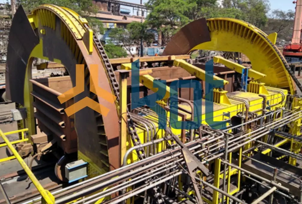
Thus, the subject of this article, the railcar dumper (or RCD, as it is known in the port and railway market), is a large piece of equipment responsible for unloading bulk material (ore, grain, etc.) transported by railcars.
First, how does this equipment work? The car enters the machine through a car pusher. Hydraulic clamps are usually used to secure the railway equipment to the structure. The VV then connects to the railcar and rotates it around its longitudinal axis, allowing the entire load to be unloaded by gravity into a hopper as the train moves forward in the terminal, assisted by the aforementioned pusher.
A Succes story
This article presents a Kot Engenharia Succes story Kot Engenharia one of its customers. The equipment user replaced the wagon turner with a new turner with a design identical to the replaced equipment. Kot visited the wagon turner beforehand and detected cracks and some structural non-conformities, as well as balancing problems.
Subsequently, our company was hired to conduct a study of the equipment, which involved the following activities:
-
- Structural analysis: static, fatigue, buckling, and metal connections;
- Mechanical analysis: drive components and hydraulic cylinders, as well as balance verification;
- Corrective actions and structural improvements.
With over three decades of experience in Structural Integrity, Kot emphasizes that design audits performed prior to manufacturing are strategic because they prevent premature failures, reduce operating costs, and extend equipment life at a reduced cost. Therefore, detecting non-conformities early in the design phase allows for less expensive interventions and increases the physical availability of the equipment.
Unfortunately, this preventive approach was not adopted at the outset, and the study was conducted with the equipment already in operation and subject to pathologies.
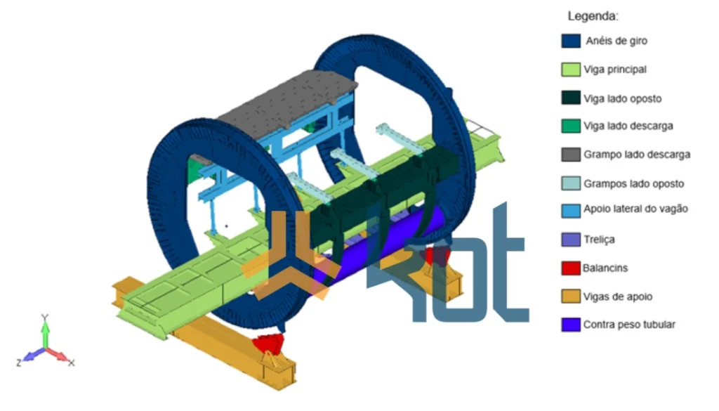
Figure 1 shows the unit's VV, and Figure 2 shows the computational model of the equipment under study with its main parts.
Structural and mechanical analyses applied to a railcar turner
1. Structural analysis
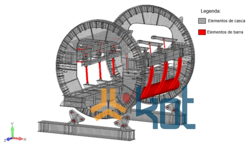
In this section, a computational model was developed using the Finite Element Method (FEM). The structure of the wagon tipper is largely composed of welded plates, which are represented in the finite element model by plate and shell elements. The hydraulic cylinders, hinge pins, and counterweight tube were modeled using beam elements. Figure 3 illustrates the location of the elements used in the construction of the computational model of the railcar turner.
Regarding the structural analysis, the MEF was used, in which the loads acting on the equipment are discretized and applied to the wagon turner arrangement, being verified under different operating conditions. Based on this, static, fatigue, buckling, and connection analyses were performed, which are described below.
1.1 Static Analysis
Static analysis in FEM is an analysis that considers that the loads and boundary conditions involved do not change over time. Therefore, this analysis considers that the stresses remain in the elastic region of the material of the structure involved. Therefore, the static analysis of the equipment is performed based on the stresses obtained in the finite element models for each component of the structure, in each of the verified load combinations. Nonlinear analysis, on the other hand, is indicated for cases in which we have nonlinear behavior of the material and large displacements, for example.
In this context, the study considered permissible stresses, safety factors, and utilization indices (UIs) specific to each component of the structure, based on the load combinations applied and evaluated.
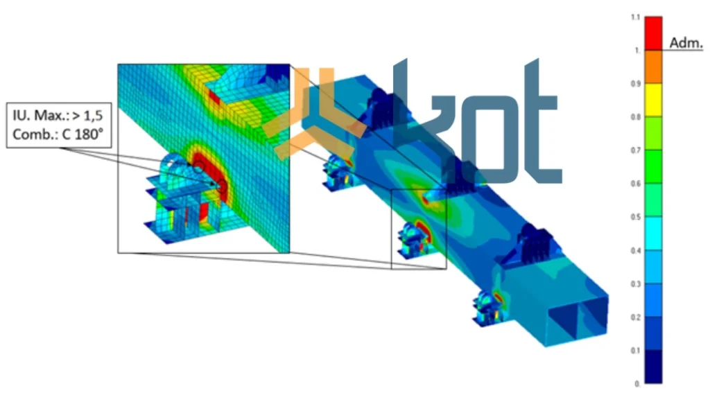
Figure 4 shows the analysis of the shell elements, in which the distribution of utilization indices in the subsets was plotted on a color scale over the model.
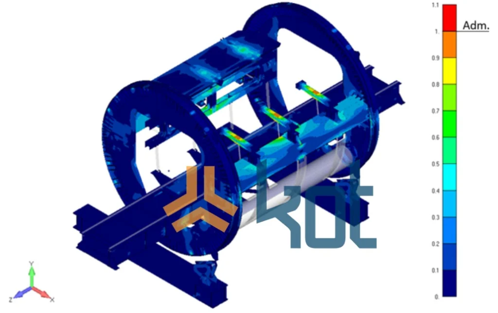
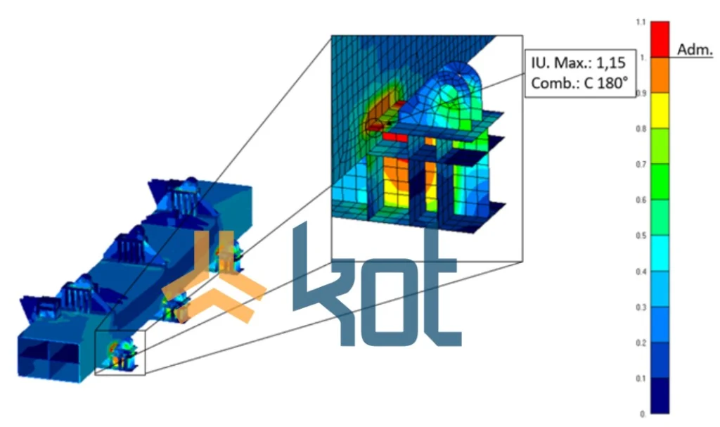
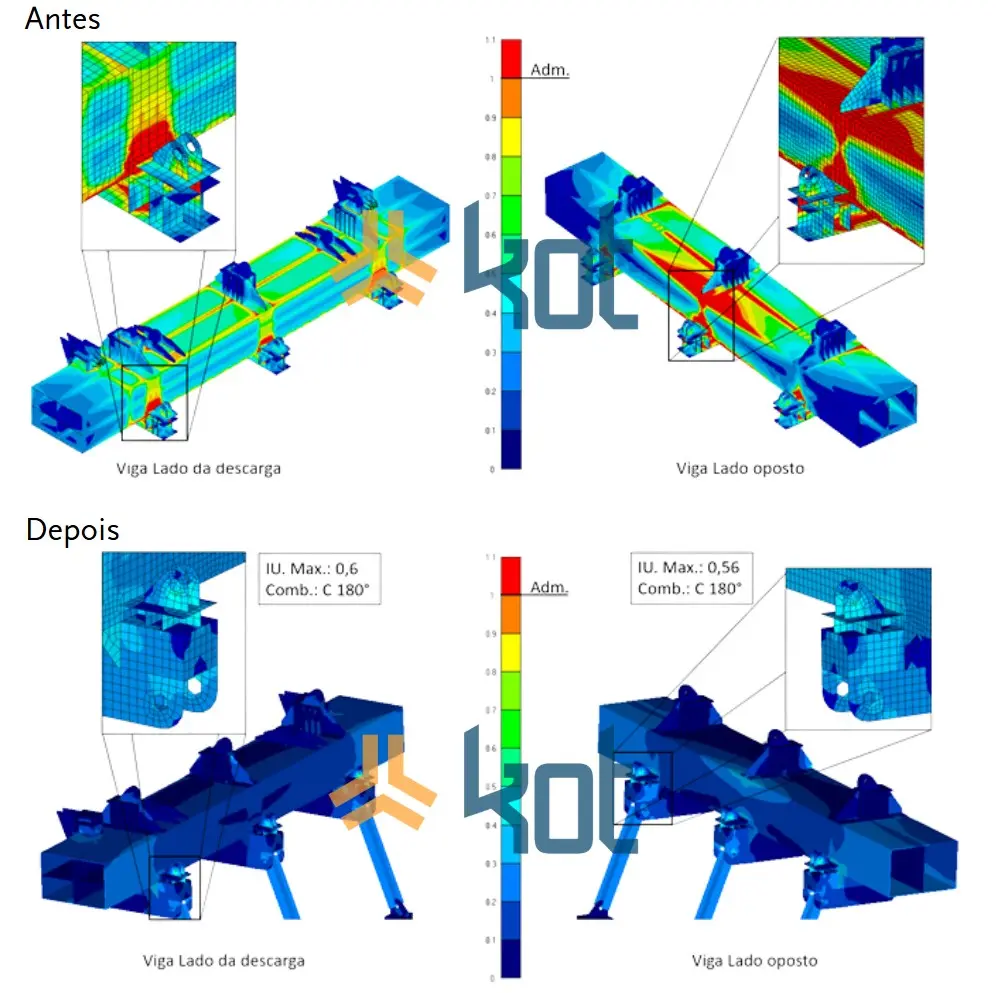
As a result, for this case (normal operation), utilization rates above the permissible level were identified in the support of the clamp cylinders for the two box girders that connect the turner mirrors, especially for the end of rotation condition. The central support of the beam opposite the discharge was the most critical region, with stresses above the yield limit being obtained in regions with stress concentrators. Figure 5 and Figure 6 show in detail the critical region for the box girders.
All other subsets complied with the criteria adopted for evaluating stresses in the elastic regime.
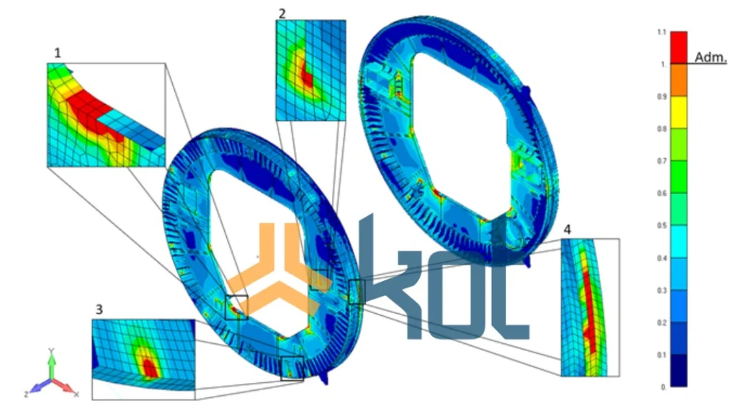
1.2 Fatigue Analysis
Fatigue analysis consists of evaluating a fatigue utilization index for each shell element of the structure, considering the variation in stresses to which it is subjected, the frequency of loading, and the stress concentrators existing in the structure.
At this stage, for fatigue analysis, the expected service life was 25 years. For loading, normal operating combinations were used. Areas were identified with a risk of cracks opening in welds and base metal with accumulated damage above the permissible level. Furthermore, this revealed that the equipment structure was insufficient to achieve the expected service life. Figure 7 and Figure 8 illustrate these points.
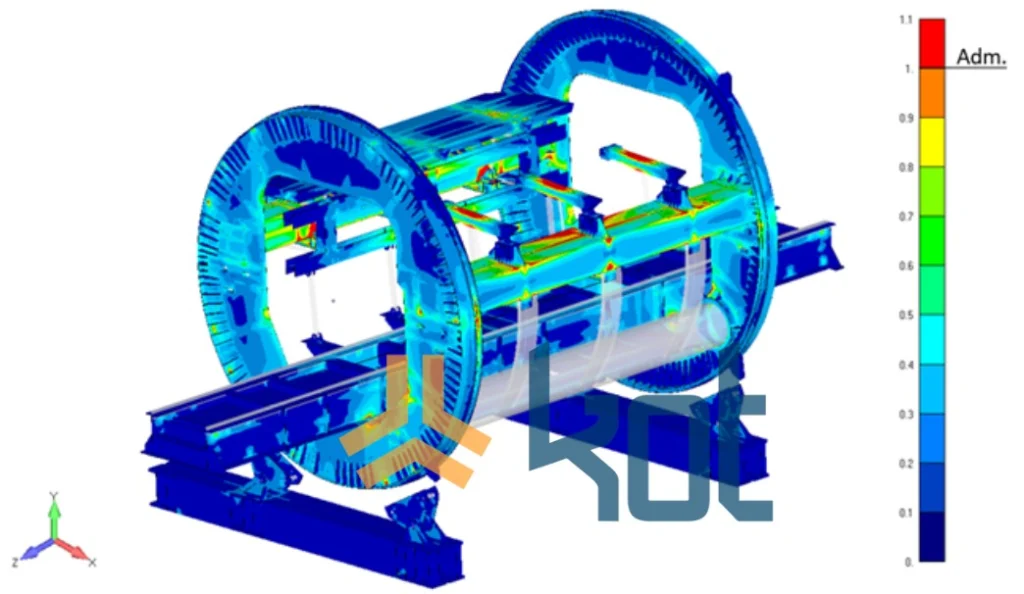
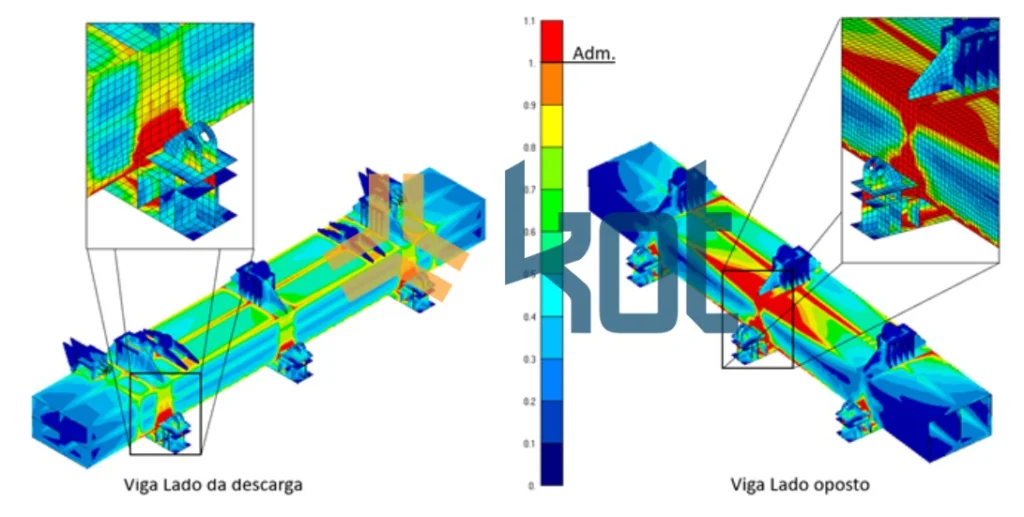
Furthermore, the slewing rings, simple clamps, and side support of the wagon also presented regions with failure in the fatigue analysis. The slewing rings showed some areas with fatigue utilization rates above the permissible level (see Figure 9), however, some of them were not considered critical. However, areas 2 and 4, for example, showed risks of fatigue failure due to the combined torsional and bending stresses imposed on the box girders.
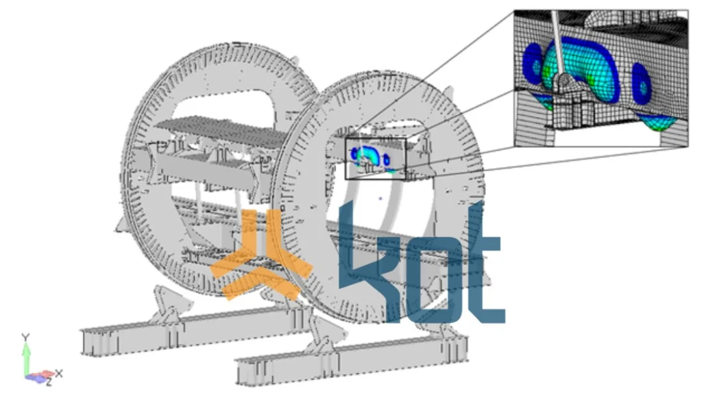
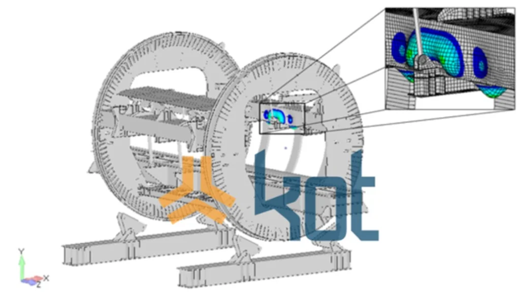
1.3 Buckling Analysis
The buckling analysis aims to identify the instability of the structure when subjected to loads, with special attention given to compression loads. The buckling phenomenon occurs when the structure no longer meets the stability criteria and deforms abruptly. In general, the analysis is important for detecting the critical buckling load, the respective buckling modes, and whether the structure will exhibit instability before reaching the yield levels.
As can be seen, Figures 10 and 11 show the eigenvectors related to the most critical eigenvalues, calculated in the buckling analysis, which were observed in the equipment structure. Thus, based on the results obtained and the evaluation of the requirements for buckling verification, it was observed that the structure met the criteria, with no risk of sudden instability of the plates.
1.4 Analysis of metal connections
Connecting elements promote the union of parts of the structure with each other or the structure with external elements. Welds, screws, threaded bars, and pins are mainly used as connecting means. Therefore, the analysis of these connections is recommended so that they can withstand the loads and stresses to which the asset is subjected.
Therefore, the analysis of the switch connections was performed in accordance with the criteria established in established engineering standards and procedures. Fortunately, all connections analyzed were approved, with no IU above 1.
2. Mechanical Analysis
2.1 Checking components and hydraulic cylinders
The analysis covered the following items:
-
- Mechanical components (required power and drive system);
- Hydraulic system (clamps and wagon support structure);
- Current (static and fatigue);
- Axles;
- Sprocket and gear wheel (bending and wear);
- Wheels.
Consequently, at the end of this analysis, some components were rejected, for example: coupling, reducer, chain, and sprocket, even with the new balancing condition that would be proposed. Therefore, it was recommended that the most suitable components for the operation be replaced.
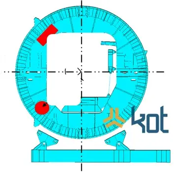
2.2 Checking the balance of the switch
Furthermore, verification of the original design balance revealed irregular power behavior as a function of the angle of rotation. This phenomenon caused sudden changes in the required torque curve at the points of concavity change, generating overloads and loss of service life.
Given this finding, a new balance was proposed for the VV and a new analysis was performed. More regular power behavior was observed as a function of the rotation angle, without sudden changes in the curve at the concavity change points. In addition, it was possible to significantly reduce the variation between the peak and vale powers vale turner's rotation cycle. This resulted in a smoother curve and better system performance. This modification reduced the stress on the drive system, increasing the service life of the components.
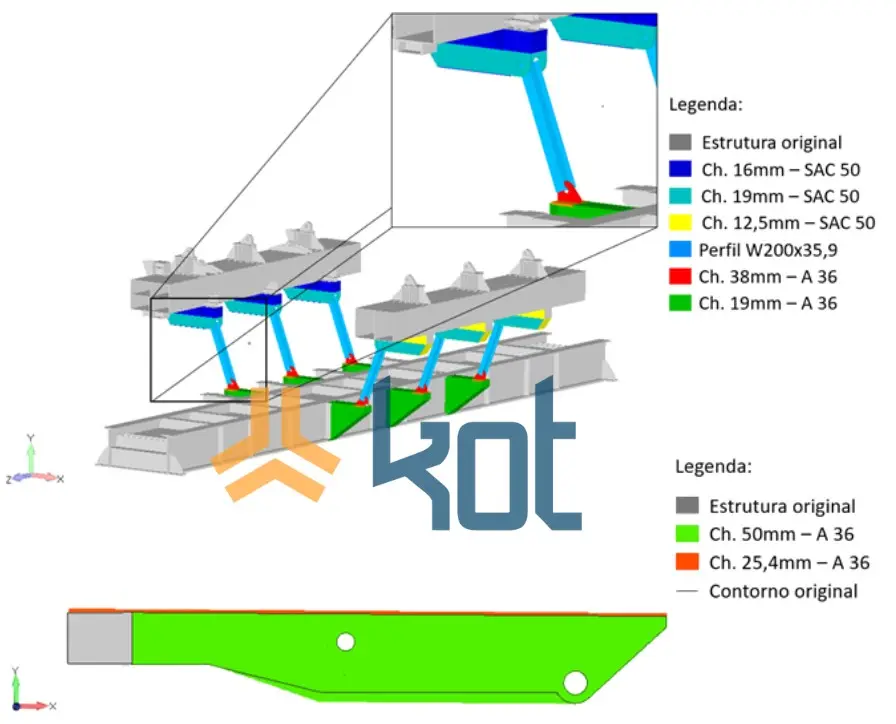
Figure 12 shows the position of the counterweights proposed by Kot to be added to the structure.
3. Required improvement actions
In addition to the rebalancing of the switch and replacement of mechanical components already mentioned, interventions were necessary in the structure of the equipment to adapt it to the requirements of resistance and fatigue life, as previously explained. In this section, we present some examples of the actions required to promote the Structural Integrity the asset.
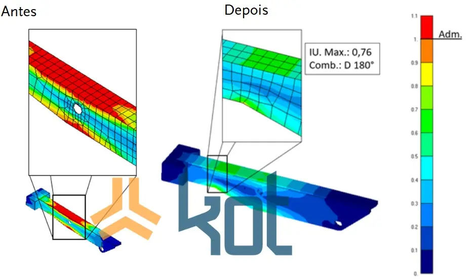
Modifications were suggested to the box beams, using tie rods to connect them to the main beam (see Figure 13), and modifications to the geometry of the simple clamps to increase bending inertia.
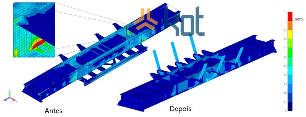
Figures 14 to 16 show comparisons of stresses for improving the Structural Integrity equipment after adopting the proposed reinforcements.
Technical results and benefits
The use of FEM for the structural analysis of railcar turners allowed for the presentation of adequate risk treatment and promoted the Structural Integrity the railcar turner. Similarly, the mechanical analysis resulted in greater reliability and will promote a reduction in unexpected downtime.
Among the benefits of the modifications and practical results of the study are:
-
- Reduced wear on mechanical components;
- Improved torque distribution;
- Lower risk of engine overheating;
- Increased equipment service life;
- Less need for corrective maintenance due to fatigue.
Contact Kot Engenharia
Are you interested in promoting the Structural Integrity your railcar turner or any other handling asset? Are you experiencing mechanical component failure in this type of asset and can't find a solution? Do as our more than 150 customers have done,consult our team and learn about our services.
Since 1993, we have been specialists in developing engineering solutions through inspections, technological tests, and the use of computational methods for complex assessments of concrete and metal structures and industrial equipment.
Follow our pages on LinkedIn,Facebook, andInstagramandkeep up with our content.
FAQ
1. Como mitigar falhas estruturais por fadiga em grandes equipamentos de manuseio de carga, como viradores de vagões?
Equipamentos dinâmicos submetidos a ciclos contínuos de carga e descarga sofrem danos por fadiga mecânica devido à variação constante de tensões nas juntas soldadas e no metal base. A mitigação eficaz exige o mapeamento dessas tensões por meio do Método dos Elementos Finitos (MEF) para identificar concentradores de estresse acima do admissível. A partir desses dados, engenheiros especialistas aplicam ações corretivas, como alterações geométricas em componentes críticos (grampos e apoios) e a introdução de tirantes estruturais para redistribuir os esforços de torção e flexão, uma metodologia frequentemente executada nos diagnósticos da Kot Engenharia.
2. Qual é o impacto do desbalanceamento dinâmico no sistema de acionamento mecânico de equipamentos rotativos?
O erro no posicionamento ou dimensionamento de contrapesos provoca um comportamento irregular da potência requerida ao longo do ciclo de rotação. Esse fenômeno gera mudanças bruscas na curva de torque nos pontos de inversão de concavidade, submetendo o trem de força a sobrecargas severas de impacto. Na prática, esse desbalanceamento causa o aquecimento dos motores elétricos e acelera drasticamente o desgaste e a quebra prematura de componentes críticos, como redutores, acoplamentos, correntes e pinhões. O rebalanceamento geométrico suaviza essa curva de potência, reduzindo a variação entre picos e vales de torque.
3. Por que a substituição de um equipamento antigo por um “projeto idêntico” novo pode perpetuar falhas operacionais?
Replicar desenhos antigos sem realizar uma auditoria de projeto preliminar induz ao erro de transferir vícios ocultos de dimensionamento ou defasagens normativas para o novo ativo. Falhas crônicas de fadiga ou erros de balanceamento original não são eliminados apenas substituindo o metal desgastado; eles reaparecem assim que a nova máquina atinge o mesmo volume de ciclos operacionais. Avaliações de engenharia com simulação computacional antes da fabricação evitam custos desnecessários com reformas emergenciais pós-comissionamento.
4. Para que servem e como são avaliados os Índices de Utilização (IU) em análises estruturais via MEF?
O Índice de Utilização (IU) é a razão entre a tensão atuante calculada no modelo computacional e a tensão admissível estipulada pelas normas técnicas para o material em questão. Um IU menor ou igual a 1,0 indica que o componente opera com segurança dentro do regime elástico. Quando o índice supera esse limite (como identificado nas vigas caixão e suportes de cilindros no estudo de caso do virador), a estrutura entra em risco de escoamento plástico ou falha local, sinalizando precisamente onde os reforços estruturais são mandatórios.
5. Qual a importância de realizar análises de flambagem em estruturas formadas por chapas soldadas?
A flambagem é um fenômeno de instabilidade geométrica que ocorre quando elementos esbeltos ou chapas finas submetidos a esforços de compressão sofrem deformações abruptas antes mesmo de o material atingir o seu limite de escoamento. Em equipamentos industriais de grande porte formados por vigas caixão, o cálculo dos modos de flambagem (autovalores e autovetores) garante que a rigidez das paredes metálicas seja suficiente para suportar cargas combinadas sem colapsar repentinamente por perda de estabilidade geométrica.


