
Introduction
The Industry 4.0 revolution has enabled the development of new techniques and technologies for various fields of engineering. In addition, one of the innovations that is becoming increasingly popular is the use of real-time monitoring systems.
In this regard, this article discusses a success story involving the company’s development of a monitoring system for a bucket wheel-type ore recovery plant. Check out the details of the project below!
First, the main function of the monitoring system that has been implemented is to ensure the stability of the equipment in accordance with the standards. As discussed earlier in this blog, for the machine to meet stability requirements, the calculated index must fall within the limits established in the applicable guidelines. Thus, for each operating condition, the coefficient value must satisfy a safety factor.
Development
Initially, the analysis of the rotation system’s stability—or local stability—was performed by monitoring the position of the center of gravity (CG). Under each operating condition, the Cartesian location of the CG in a coordinate system must comply with limits established by safety factors.
Second, to meet the overall stability requirements, a flowchart was developed to determine which stability case the machine is operating under, based on wind and material flow conditions. For example, a simplified version of this flowchart is shown in Figure 1.
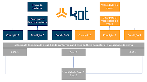
Figure 1: Global stability flowchart. [1]
According to the standard, it is possible to assign three different safety factors, which vary depending on the operating conditions; each case can be defined as follows:
-
- Stability Case 1: indicates that the system is stable for the normal operating condition;
-
- Stability Case 2: indicates that the system is stable for an abnormal operating condition;
-
- Stability Case 3: indicates that the system is stable for an exceptional operating condition.
Since the values that define the material flow and wind speed conditions are specified by the machine design and the standard, the system was designed so that these parameters are configurable. Thus, these parameters can be adjusted to suit other machines and/or scenarios.
Subsequently, after these cases and scenarios were defined, the data acquisition systems were installed and calibrated, and the system logic was implemented in the programmable logic controller (PLC). To make it easier to monitor the machine’s stability status, the Human-Machine Interface (HMI) screen was modified.
In addition, a real-time machine stability indicator has been added to the HMI. The indicator, located in the upper-left corner of the screen, displays a green triangle for Stability Case 1, a yellow triangle for Stability Case 2, and a red triangle for Stability Case 3. For illustration purposes, Figure 2 shows the display in the reclaimer’s operator cab.
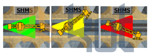
Figure 2: Indicator present on the HMI screen in the 3 stability cases. [1]
In addition, the boom belt conveyor and the bucket wheel are also equipped with real-time indicators. When the indicator is green, it means the equipment is stopped. When it flashes yellow, it indicates that the equipment is malfunctioning. When it is red, it indicates that the equipment is operating.
Similarly, Kot made changes to the control room’s supervisory monitoring system to display all information related to the machine’s operational integrity. To that end, two screens were developed.
-
- Main screen: the main screen contains all the machine's information. The top left corner shows information on the forces on the forklift's supports. The top right corner shows the system's stability information, with graphical bars and trend graphs. Figure 3 shows a screenshot of this screen.
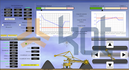
Figure 3: Supervisory system with simulated values. [1]
-
- Configuration screen: the second screen created is the screen for entering the machine's configuration data.
Conclusion
A recent post discussed the mathematical and computational verification of yard crane stability. Accordingly, building on this concept and in line with Industry 4.0, Kot has developed a system capable of monitoring stability data in real time.
As a result, the implementation of this technology can bring several benefits to the operation, since it provides greater control over the monitored asset and helps prevent undesirable events, thereby contributing to increased safety and reduced environmental impacts, while also boosting the mine’s productivity.
In short, the concept ofthe “Mine of the Future” is precisely about automating processes, enabling preventive maintenance of equipment. It is in this context that Kot offers its stability monitoring service, allowing customers to boost their business results.
If you, like our more than 150 clients, are looking for engineering solutions for your operation, contact our team and find out more about our services. Since 1993, we have specialized in developing engineering solutions using computational methods.
Follow our pages on LinkedIn, Facebook e Instagram to keep up with our content.
References:
[1] Kot Engenharia Collection.


