
The investigation of anchor failure requires an integrated analysis of concrete, steel, and foundation. Recently, Kot Engenharia conducted a comprehensive study on mining equipment that suffered anchor bolt failure, identifying the causes of the failure and proposing safe and easy-to-implement solutions. So, read on and find out how diagnostic engineering prevents unscheduled downtime and increases structural reliability.
1. Analysis of Anchor Failure: Initial Diagnosis
Metal structures and industrial mechanical equipment generally have some connection with reinforced concrete elements. This interface is usually made using anchor bolts, which are anchored in the concrete in order to transmit the forces from the supported components. This article will discuss one of Kot Engenharia success stories, in which a failure analysis was performed on the base connection of a piece of mining equipment. Consequently, the anchor bolts of this equipment broke, causing it to tip over, as shown in Figure 1. Therefore, the analysis aimed to identify the causes of the failure and propose solutions so that the equipment could return to operation safely.
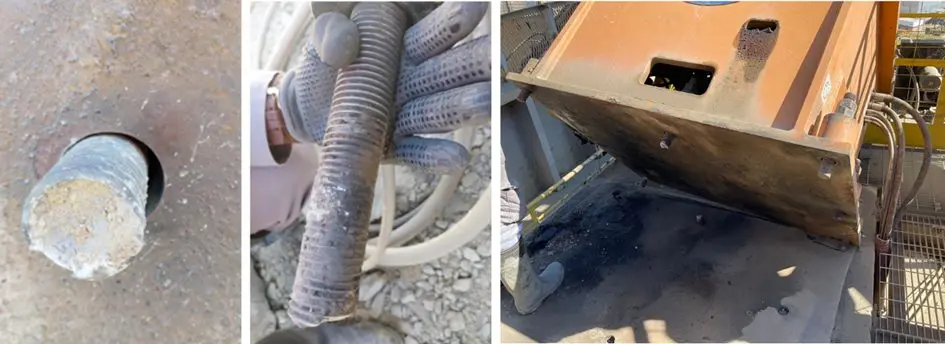
Figure 1: Faulty connection at the base of the equipment.
2. Methodology employed
2.1. Analysis of stresses and evaluation of anchor bolts
The failure investigation consisted of an analytical stage to check the transmission of forces between the components of the steel-concrete connection, and a computational stage to check the foundation footing supporting the equipment. In this way, as well as identifying the cause of the failure, it was also possible to assess the conformity of the structure's design.
The dimensioning of anchored connections must take into account the combined behavior of the materials involved. Therefore, both the failure modes related to concrete and the limit states associated with the anchor steel must be verified in order to define the materials and dimensions of the connection elements. Figure 2 shows the failure modes that can occur in this type of connection.

Figure 2: Failure modes associated with anchored connections.
Initially, based on the equipment load plan, the stresses on the connection components were determined. The machine analyzed was supported on a layer of rubber, used to absorb the vibration developed during its operation. Thus, in addition to the traction and shearing on the anchor bolts, the lever arm due to the rubber led to the development of bending moments on the anchor bolt bars, which proved to be the critical stress in the analysis.
In addition, the dynamic nature of the equipment loads was also considered. Based on the defined stresses, the stresses in the cross section of the anchor bars were calculated to verify material fatigue. Additionally, as the equipment can operate in different directions, the stresses caused by the bending moment on the bar can be either compression or tension, as shown in Figure 3, causing a large variation in stresses.
Figure 3: Representation of the equipment's movement during operation.
Finally, considering the high magnitude of the stresses, fatigue analysis indicated that even a small number of equipment operating cycles could lead to a reduction in the service life of the lead weights, justifying the failure that occurred. This conclusion was corroborated by a metallurgical analysis performed on the broken metal, which found that the fracture surface exhibited cracks with characteristics typical of nucleation and propagation due to fatigue under bending stress, followed by a brittle fracture of the remainder of the section. Failures in the manufacturing process of the lead weights were also identified and contributed to their rupture.
2.2. Computational modeling
The finite element model of the foundation footing was used to perform structural and geotechnical checks. During this stage, it was observed that the base of the footing had a compressed area below the minimum value recommended by the standard, indicating a risk of loss of stability of the structure.
3. Proposed solutions
To restore the connection between the equipment and the concrete, the proposed solution was to use padlock-type anchors, which are embedded in steel tubes embedded in the concrete. With this system, the base can be restored without the need to demolish the concrete, requiring only the drilling of holes to remove the broken anchors and install the new tubes. In addition, the anchor bolt maintenance process is simplified and can be performed without removing the equipment.
Similarly, a prestressing value was recommended for tightening the anchor bolts to prevent load variations in the bars during equipment operation. The proposed system can be seen below in Figure 4.
Figure 4: Representation of the proposed system for fixing the equipment.
To prevent shear forces from being transmitted to the foundation by the anchor bolts, it was proposed that a shear plate be installed at the base of the equipment. It was also recommended that the rubber layer on the base be replaced with a high-strength grout capable of leveling the base and withstanding the vibrations caused by the operation of the equipment.
To solve the design non-compliance related to the stability of the foundation, an increase in the height of the footing base was proposed, as shown in Figure 5. In this way, the region with loss of contact between the structure and the ground is reduced to the permitted normative range, in order to ensure the safety of the foundation.
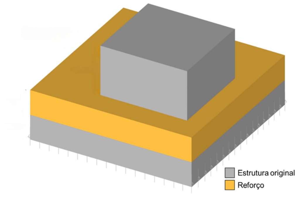
Figure 5: Proposed solution for reinforcing the footing.
4. Impact of the anchor failure investigation analysis and proposals for improvement
The analyses conducted identified the cause of the failure of the lead connection: the rubber layer at the base of the equipment acts as a lever, increasing the shear force on the lead anchors and causing the metal to break. In addition, the computational approach also identified a non-compliance in the foundation design related to the stability of the structure.
The work carried out led to the proposal of solutions for the problems identified. Thus, the proposed changes aim at safety for equipment operation and are easy to implement and maintain throughout their useful life.
Therefore, the evaluation of connections between steel and concrete elements must be carried out taking into account the joint behavior between these materials and the specific limit states associated with this type of connection.
5. Failure analysis is done by Kot Engenharia
If you, like our more than 150 clients, are looking for specialized solutions in structural analysis or failure prevention such as deformation, vibration, and corrosion, consult our team and count on Kot Engenharia.
Since 1993, we have been offering engineering consulting services through technical studies using non-destructive testing, field instrumentation, and computational simulations (FEM, DEM, and CFD) for highly complex diagnostics in concrete and metal structures and industrial equipment.
Follow our pages on LinkedIn,Facebook, and Instagram to keep up with our content.
FAQ
1. Como uma camada de amortecimento de borracha conseguiu induzir a quebra dos chumbadores por fadiga?
A borracha possui alta flexibilidade. Sob a ação de forças dinâmicas horizontais (cisalhamento), ela se deforma elasticamente e cria um vão livre, atuando como um braço de alavanca mecânico nas barras dos chumbadores. Em vez de sofrerem apenas tração ou corte puro, os chumbadores passaram a suportar momentos fletores (flexão) cíclicos e alternados. À medida que a máquina operava em diferentes direções, as barras sofriam ciclos violentos de tração e compressão. Essa oscilação contínua de tensões causou a nucleação e a propagação de trincas por fadiga, destruindo a vida útil do metal até a sua ruptura frágil repentina.
2. Por que a solução proposta utilizou chumbadores tipo “cadeado” combinados com a aplicação de protensão?
Os chumbadores tipo cadeado são alojados dentro de tubos de aço embutidos na própria fundação de concreto. Esse arranjo facilita muito a manutenção: se uma barra falhar ou precisar de substituição no futuro, o processo é feito sem quebrar o bloco de concreto e sem remover o equipamento da base. Já a protensão (o torque de aperto controlado) traciona previamente a barra de aço de forma tão intensa que as cargas dinâmicas da operação da máquina não conseguem alterar o seu nível de tensão interna. O chumbador passa a trabalhar sob uma carga estática constante, blindando o metal contra o ciclo de fadiga.
3. Que outras não conformidades ocultas foram reveladas pela modelagem computacional da fundação?
A análise por Elementos Finitos (MEF) revelou que o problema estrutural era mais profundo do que a quebra dos parafusos. O dimensionamento geométrico da sapata de fundação apresentava um erro crítico: sob as piores combinações de carga da operação do equipamento, a área da base da sapata que permanecia efetivamente comprimida contra o solo estava abaixo dos limites mínimos exigidos pelas normas técnicas. Havia um risco real de perda de estabilidade geotécnica por tombamento do bloco inteiro. Para mitigar o problema com segurança, recomendou-se o aumento da altura da base da sapata, corrigindo a distribuição de pressões no solo.


