
If your company operates in the infrastructure, transportation, or large-scale construction sectors, understanding the importance of Project Quality Control (PQC) certification is essential to ensuring the safety and reliability of structures. In addition, Kot Engenharia a national leader in Structural Integrity advanced engineering solutions. Continue reading and discover how PQC can raise the technical standard of your projects.
1. Why Project Quality Control (PQC) is essential for large-scale construction projects
Project Quality Control (PQC), also known as Project Quality Certification or independent review, is an essential step in ensuring that a structure fully meets the safety, durability, and performance requirements demanded by technical standards. In fact, this process is especially relevant in large-scale projects, such as bridges and highway overpasses, whose complexity requires coordination between different construction phases and engineering disciplines.
In Brazil, project conformity assessment is provided for in standards such as ABNT NBR 6118:2023 (item 5.3) and ABNT NBR 16694:2020 (item 5.2), both recommending that this analysis be conducted by a qualified professional other than the project author. In addition, complementary guidelines, such as those issued by public agencies, transportation authorities, or specific customer standards, may reinforce the mandatory nature or recommendation of this independent technical review.
As an example, this article presents a real case study of an analysis conducted by Kot Engenharia the structural certification of a road viaduct, including computational modeling using the Finite ElementMethod (FEM), regulatory verification, and structural performance evaluation.
Consequently, the analyses carried out by Kot were compiled in an independent report, which, in addition to verification based on the information in the executive package, examined regulatory compliance, integrity criteria, and the structural performance of the work.
2. Practical application of Project Quality Certification: case study on a highway overpass
2.1. Structural description of the special work of art (SWA)
The OAE, the object of study, refers to a road viaduct composed of precast beams in a mixed steel-concrete structure. Photographs and drawings of the Object can be viewed in Figure 1 to Figure 2.
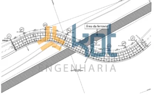
Figure 1: Plan view of the OAE.
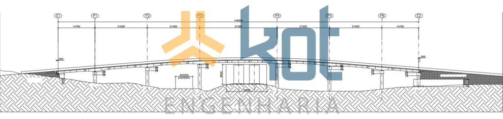
Figure 2: Elevation view of the OAE.
According to the conventional subdivision nomenclature adopted for OAEs, the viaduct in question consists of:
- Mixed steel and concrete superstructures: composed of metal crossbeams and stringers, connected to a precast concrete deck. Thus, the connection between the stringers and the concrete slab is made by means of shear connectors (stud bolts), positioned in niches for subsequent final concreting on site;
- Meso-structure: composed of a crossbeam and two precast reinforced concrete pillars, forming a portico per axis. Thus, the interface between the superstructure and the meso-structure is made by means of circular elastomeric support devices with prestressed tie rods to the crossbeams, ensuring contact in various operational scenarios. These devices are supported by concrete shims of varying heights, used to configure the road superelevation of the deck.
- Infrastructure: composed of 15 blocks of continuous flight pile caps, with a diameter of 50 centimeters. A special detail occurs in the connection between the infrastructure and the mesostructure, carried out by means of a cup for positioning the precast pillars, with final addition of concrete in situ in the shear key. The blocks have four distinct typical configurations in terms of the number of crowned piles, varying between six, eight, twelve, or fourteen.
1.1 STRUCTURAL MODELING USING FEM
For the structural analysis of this case, numerical models based on the finite element method (FEM) were adopted. Thus, one-dimensional, two-dimensional, or three-dimensional elements were applied according to the geometry of each structural component. In addition, simplified models were developed to obtain specific responses with greater urgency, as requested by the structure owner.
In this context, one of the first advantages of performing the CQP is the requirement for a detailed assessment of the information contained in the project's executive package, which is necessary for both geometric representation and load surveys. This process naturally generates questions and answers that allow for initial validations and corrections, as in the following cases:
- In terms of the structural concept, is there anything in the design that needs to be reconsidered?
- : The details may present weaknesses, inadequacies in terms of the number of connections, or other inconsistencies that can be identified without performing calculations. Is the foundation methodology adopted compatible with the results of the soil survey and characterization provided?
- Have structural and non-structural materials been specified correctly?
- : Whether incompatible metals are specified in the design or whether the reinforcement cover of concrete parts is compatible with the environmental aggressiveness class.
- Is the basic general information about the project presented satisfactorily?
- : Quotas, views, elevations, details, etc.;
- Is the information presented consistent with each other?
- : Whether the dimensions shown in different views differ or not.
- Is there sufficient information about the details and accessories?
- : Welding methodology, screw diameter, cutting and bending of bars, definition of fenders, etc.
In this way, even initial questions and answers contribute to raising the maturity level of the project, resulting in greater efficiency and safety during construction for all parties involved.
Subsequently, structural modeling in FEM will allow for agile simulation of the structure's behavior under different loading conditions, increasing the range of available results.
2.2.1. Geometry
Due to deadlines and the diversity of disciplines involved not only in OAE projects, but also in other structures, it is common for the dimensioning of structural subsets to be carried out by different companies. For example, the metal/concrete structural design, foundations, and interfaces between these elements can be carried out by different designers, who communicate with each other through load plans.
Therefore, another potential benefit of FEA is the possibility of simulating overall structural behavior considering the interaction between subsets or disciplines, an approach adopted in this case. In addition, earthworks such as cuts or embankments, or even the presence of new adjacent structures, can cause displacements in the infrastructure that generate significant stresses in the superstructure. Thus, this type of impact is more easily assessed when the modeling considers the entire project.
Figures 3, 4, and 5 show the computational model used to analyze construction and operating conditions.
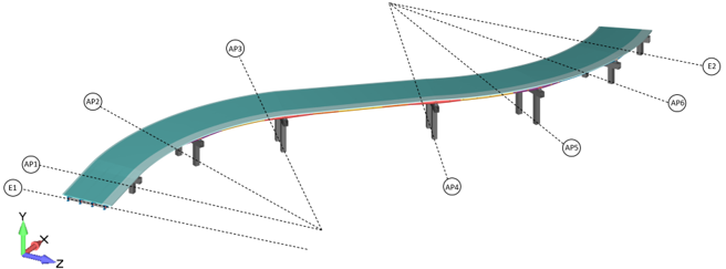
Figure 3: Overview of the computational model including superstructure and mesostructure.
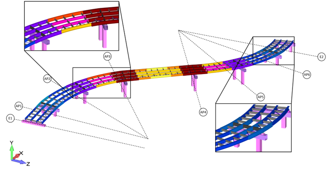
Figure 4: View of the computational model highlighting the metal stringers and crossbeams of the superstructure.
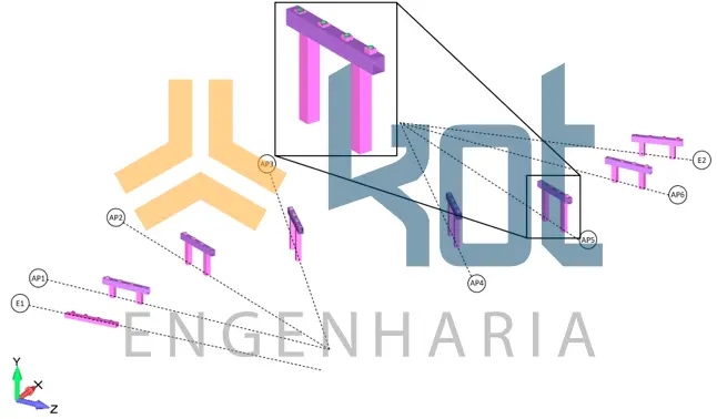
Figure 5: View of the computational model highlighting the crossbeams and pillars of the mesostructure.
For more detailed analyses of stresses and stability of the superstructure stringers, Kot also developed a secondary model representing the stringers and their ribs using two-dimensional elements, shown in Figure 6.
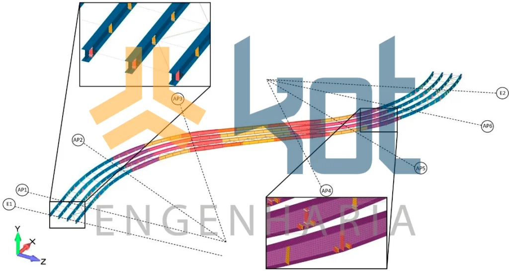
Figure 6: Computational model of the metal stringers of the superstructure in shell elements.
Finally, as shown in Figure 7, piles and infrastructure cap blocks were represented in one-dimensional and three-dimensional elements, respectively.
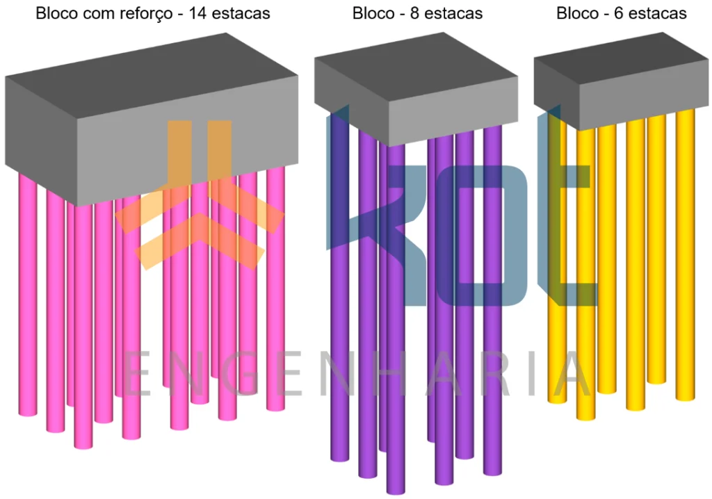
Figure 7: Pile blocks in a computational model.
2.2.2. Shipments considered
Next, the loads acting on the structure are identified, which were combined according to the Brazilian regulatory algorithm for verifying the structure in various normal, special, and exceptional usage scenarios:
- The structural dead weight was determined considering the values indicated in the reference documents;
- Non-structural dead weight also determined according to the indications in the design documents;
- Road freight transport, in accordance with Brazilian regulatory requirements;
- Longitudinal braking and acceleration force on the viaduct deck;
- Centrifugal force on work on a horizontal curve;
- Effects of uniform temperature variation;
- Forces due to wind action against the structure;
- Shrinkage due to concrete curing, considering a linear action in the deck region;
- Side impact on restraint device;
- Construction overload.
2.3. Summary of assessments conducted by Kot
Due to the fact that it is a mixed steel and concrete structure, several checks were carried out both during the construction phase, when the metal structure supports the weight of the concrete in a plastic or unbound state, and during operation, considering the interaction between these materials.
Additionally, given that the primary concrete structure components were precast (concreted outside their final position), additional checks were carried out on the integrity of these members under hoisting conditions, as well as on the reinforcements used in this process, such as eyebolts.
Next, for the sake of objectivity, the main assessments of the key elements of the OAE under operating conditions are presented.
2.3.1. Evaluation of the superstructure and mesostructure
- Structural analysis of the deck: This consisted of verifying the resistance capacity of the reinforced concrete sections to simple bending and shear forces acting on the reinforcement arranged in the transverse direction of the viaduct, in accordance with the criteria set out in NBR 6118. As this is a composite beam structure, the reinforcement arranged in the longitudinal direction was evaluated together with the stringers.
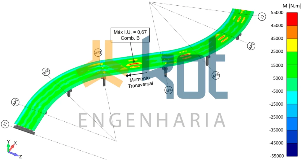
Figure 8: Distribution of maximum bending moments in the deck slab in the transverse direction.
- Mixed steel and concrete stringers: Analytical verification of the bending and shearing of the stringers was performed with total interaction of the deck slabs, constituting the mixed steel and concrete beam structural system. These composite profiles were analyzed in accordance with the requirements of Annex O of standard NBR 8800 in sections with higher values of positive, negative, and shear bending moments in each of the spans.
- Crossbeams and bracing: The crossbeams and bracing that make up the metal structure of the viaduct were verified as isolated profiles (without interaction with the concrete) in accordance with AISC 360-10. Based on the stresses derived from the finite element calculation, each profile was evaluated individually, in accordance with regulatory criteria.
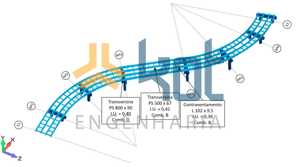
Figure 9: Highest I.U.s obtained in the verification of crossbars and bracing.
- Pillars: The structural analysis of the viaduct pillars considered the resistance capacity of the reinforced sections under composite oblique bending and shear stress, in accordance with NBR 6118 criteria;
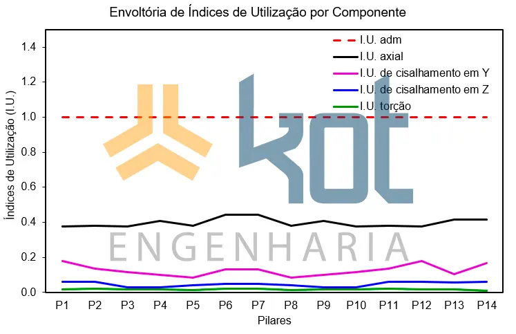
Figure 10: Envelope of usage indices in pillars.
2.3.2 Infrastructure assessment
The demanding efforts obtained through computational models supported the verification, considering three aspects:
- Verification of the capacity of the crowning blocks: the resistance of these parts was evaluated using the connecting rod and tie rod method. In addition, the resulting internal stresses were analyzed, obtained using free-body diagrams in critical sections, considering composite oblique bending, based on the interaction diagram.
- Structural verification of piles: assessment of the structural strength of piles (concrete section and reinforcement) was performed using internally developed software. Thus, the strength values of the materials were weighted according to the coefficients indicated by technical standards. Therefore, the analysis verified the capacity of reinforced concrete sections for composite oblique bending, also using the interaction diagram;
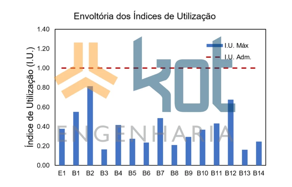
Figure 11: Envelope of stake usage indices – structural.
- Geotechnical verification of piles: soil-structure interaction assessment was conducted to determine the soil's resistance capacity, based on information obtained from the site survey report. The surveys described the layers crossed, the penetration resistance indices (NSPT), water levels, and soil characteristics. For this verification, the results obtained by the Aoki-Velloso-Monteiro method were used, applied to the lateral and tip resistance of the piles.
For this geotechnical verification, the results obtained by the Aoki-Velloso-Monteiro method were chosen for lateral and tip resistance of the piles. Figure 12 shows the diagram for the utilization index considering the maximum axial stress calculated in the operating scenario and the estimated load capacity according to the methodology described above. Approval of the piles for this criterion was also indicated;
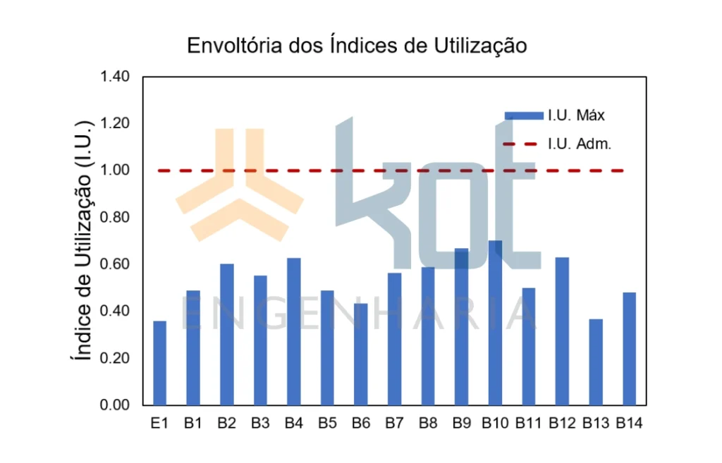
Figure 12: Envelope of pile utilization indices – geotechnical. (Figure 9)
2.3.3. Analysis of structural connections
- Chalices: the chalice inspection included the evaluation of vertical and horizontal frames, the contact stresses developed by the walls and base, as well as the verification of the composite oblique bending in the hollow section at the base of the chalice;
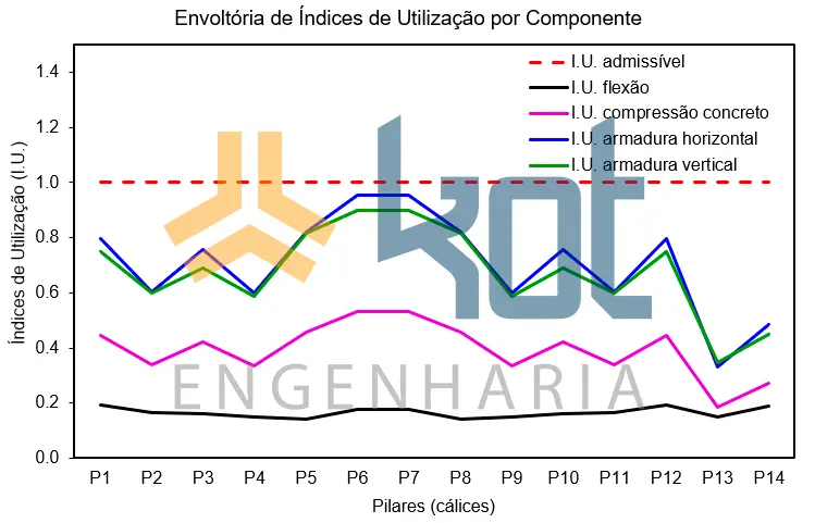
Figure 13: Envelope of usage rates – Chalices.
- Support devices: The checks carried out on the support devices covered structural capacity—including resistance to compression and shearing—and system stability. Thus, it was verified that the compression stress was sufficient to resist the tendency of the stringers supported on the elastomer to slip. In this case, prestressing was adopted between the stringers and cross members in order to ensure the necessary compression.
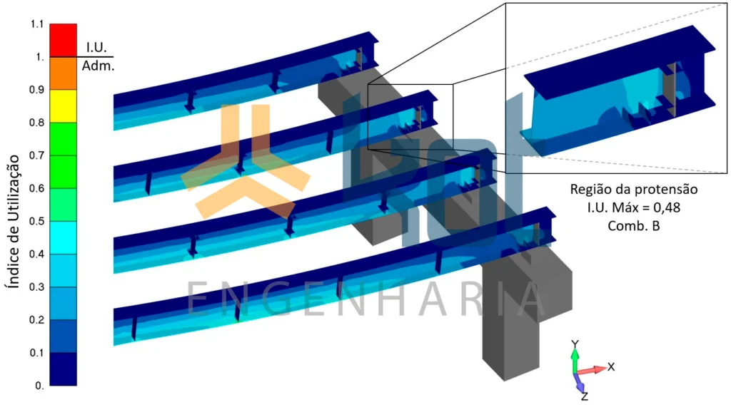
Figure 14: Local verification of the stringers considering the effects of prestressing applied between these parts and the crossbeams.
2.3.4. Analysis of excessive displacements
The verification for the service limit state of the stringers used the normative criterion of total displacement in the beam, taking into account the existence of counter-deflection specified in the design; these parts were approved for this evaluation criterion.
Like the beams, the displacements of all columns remained within the regulatory tolerance limit for SLS (Serviceability Limit State).
Finally, no non-conformities were identified in the support devices, even for load combinations that took centrifugal and braking forces into account. Therefore, the support devices are approved for in-service verification.
3. Project Quality Control Results: safety, efficiency, and investment protection
As a result of the detailed study conducted by Kot, the viaduct structure was approved after careful analysis based on the technical requirements for road viaduct structural certification, ensuring its safe release for construction and use.
In other words, independent review of structural designs is more than just a technical regulatory requirement; it is also a way to protect investments in critical assets through a preventive approach to accidents, structural anomalies, and other undesirable events. Thus, technical certification of critical aspects of the structure can identify and correct flaws and incompatibilities before they become real, which translates into greater safety, reduced rework, and protection of the project's reputation.
4. CQP is with Kot Engenharia
If you, like our more than 150 clients, are looking for specialized solutions in structural analysis or failure prevention such as deformation, vibration, and corrosion, consult our team and count on Kot Engenharia.
Since 1993, we have been offering engineering consulting services through technical studies using non-destructive testing, field instrumentation, and computational simulations (FEM, DEM, and CFD) for highly complex diagnostics in concrete and metal structures and industrial equipment.
Follow our pages on LinkedIn, Facebook and Instagram and keep following our content.
5. FAQ
1. Is the CQP required by law, or is it merely a recommendation in the standards?
There is no single federal law that mandates a CQP for every construction project, but the country’s main structural standards (ABNT NBR 6118 and NBR 16694) make it clear that an independent review is essential to certify compliance. In addition, the vast majority of public agencies, highway and railroad concessionaires, and insurance companies require a CQP report as a prerequisite for approving financing, issuing permits, or allowing construction to begin.
2. How is the CQP actually paid for? Isn't it just another project cost?
On the contrary, it acts as a safeguard against rework. The cost of correcting a geometric interference or a foundation calculation error on a computer screen is virtually zero. If that same error goes unnoticed and is discovered only once the machinery is on the construction site, the losses due to delays, wasted concrete, and work stoppages can easily cost 10 to 20 times the cost of the entire engineering review service.
3. How can we balance the tight construction schedule with the time needed for technical review?
This is the biggest bottleneck for construction companies. Ideally, the CQP should not be conducted “after” the entire project is complete, but rather in phases. Kot, for example, conducts the review in parallel with the delivery of the design disciplines (foundations first, mesostructure next, and superstructure last). This way, the construction company can begin excavation of the piles that have already been certified while the rest of the structure is still undergoing computer modeling.
6. Bibliography
- American Institute of Steel Construction. AISC 360-10 – Specification for Structural Steel Buildings. Chicago, 2010.
- Brazilian Association of Technical Standards.NBR 6118:2023–Design of concrete structures. Rio de Janeiro, 2023.
- Brazilian Association of Technical Standards.NBR 8800:2008–Design of steel structures and composite steel and concrete structures in buildings. Rio de Janeiro, 2008.
- Brazilian Association of Technical Standards.NBR 7188:2013–Mobile road and pedestrian loads on bridges, viaducts, walkways, and other structures. Rio de Janeiro, 2013.
- Brazilian Association of Technical Standards.NBR 16694:2020–Design of steel and steel-concrete composite road bridges. Rio de Janeiro, 2020.
- Brazilian Association of Technical Standards.NBR 8681:2003–Actions and safety in structures. Rio de Janeiro, 2003.
- Brazilian Association of Technical Standards.NBR 7808:1983–Graphic symbols for structural designs. Rio de Janeiro, 1983.
- Brazilian Association of Technical Standards.NBR 14724:2011–Presentation of academic papers. Rio de Janeiro, 2011.
- Brazilian Association of Technical Standards.NBR 6022:2018–Information and documentation – Scientific article – Presentation. Rio de Janeiro, 2018


