
Introduction
Structural inspection and analysis are important tools for ensuring the Structural Integrity an asset. In addition, they can be used, for example, to identify potential design flaws, investigate unforeseen or unknown phenomena, and provide technical support for maintenance planning.
To that end, to learn more about these methods in practice, take a look at a success story from Kot Engenharia. Next, this article will provide an overview of the study, including information on the sequence of the work carried out, the nonconformities identified, and Kot’s role in correcting these deviations.
To review the basic concepts of the Finite Element Method (FEM) and Visual Inspection, check out the articles:
Structural Inspection of Slag Car
Kot conducted an inspection of a slag car at a steel mill. To do so, the condition of the structures was assessed using visual inspection, penetrant testing, and dimensional analysis, with the goal of identifying nonconformities and recommending the necessary measures to ensure the equipment is fit for safe operation.
First, a visual inspection was conducted to assess the equipment’s overall condition, looking for signs of deformation and warping. In addition, the main welded joints were inspected, and an evaluation was performed to identify any deformed profiles or plates, as well as design modifications. Furthermore, nondestructive testing was performed to check for possible cracks in the structure, and several nonconformities were found. On the chassis, for example, the points shown in Figure 1 are particularly noteworthy.
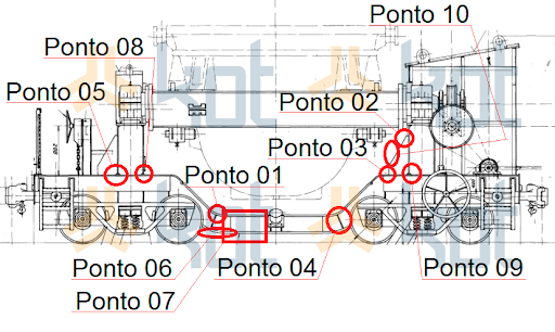
Figure 1: General view of the chassis, with identification of the points observed [1].
At point 01 there is a weld in which a crack was observed in the transverse direction of the slag carriage's rolling path, illustrated in Figure 2. This crack was observed in the table of the box profile that forms the chassis.
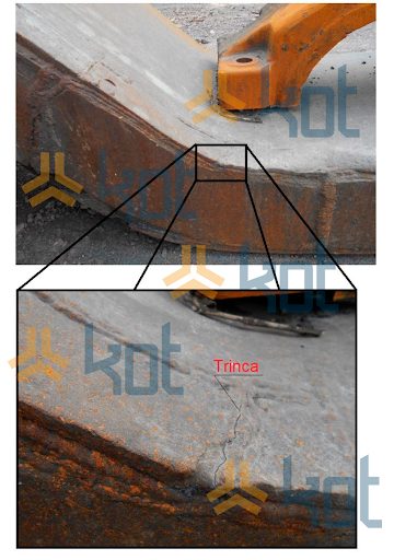
Figure 2: Crack in the transition beam of the chassis [1].
In addition, Figure 3 shows the results of the penetrant testing, revealing a discontinuity on the surface of the weld area.
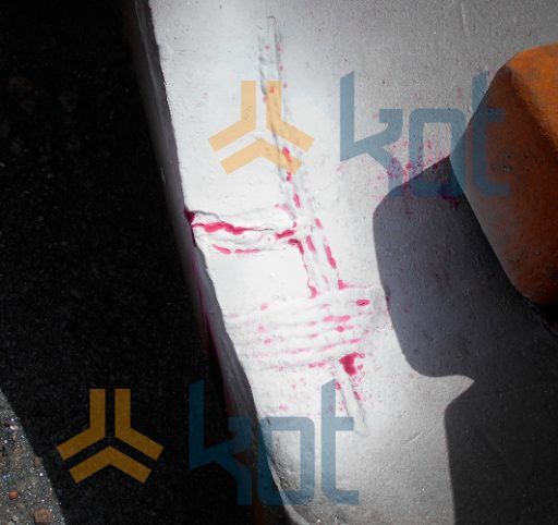
Figure 3: Evidence of the liquid penetrant test [1].
After analyzing the inspection findings, it became clear that, since the defects were distributed across all the main structures, the safe operation of the equipment was compromised. For this reason, Kot conducted a structural analysis of the car to identify areas of concern in the structure and assess the possible causes of the problems observed in the field.
Structural Analysis of a Slag Trolley
In addition to the nonconformities identified during the inspection, a finite element model was developed for simulation, taking into account the design operating conditions, the current field conditions, and the analysis criteria described in the applicable standards. The study then covered static, fatigue, and buckling analyses of the slag car components. The model and the simulation results can be seen in Figures 4 through 7.
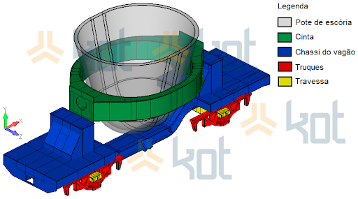
Figure 4: Finite element model of the slag car [1].
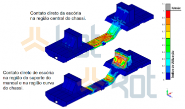
Figure 5: Utilization rates considering different contact regions [1].

Figure 6: Effect of temperature rise on the belt structure for the pot loading condition [1].
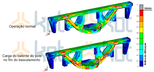
Figure 7: Influence of the pot stop load at the end of tilting on the bogie structure - spring working as a solid body [1].
Consequently, Kot Engenharia the areas of concern, analyzed the results of its simulations, and developed solutions that include replacing parts of the equipment. In short, the study made it possible to modify the slag car to ensure a safe operating cycle.
Kot Engenharia has the experience and resources needed to carry out simulations on tank sides and evaluate problems such as those described in this article. Contact our team to find out more about our solutions and how we can help your business!
Follow our pages on LinkedIn, Facebook e Instagram to keep up with our content.
References:
[1] Kot Engenharia Collection.


