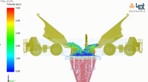

Excessive vibrations in large conveyor drive systems (such as ship loaders) drastically reduce the service life of components and threaten operational safety. In this case study, Kot Engenharia the drive base of a boom conveyor by integrating field measurements (accelerometers and high-speed cameras) with Finite Element Modeling (FEM). The diagnosis identified imbalance issues and risks of resonance, a dynamic phenomenon that occurs when the system’s excitation frequency equals its natural frequency:Excitation Frequency is approximately equal to Natural Frequency.
The solution involved the design and field validation of structural reinforcements to alter the assembly's stiffness, as well as non-destructive testing of the welds.
Would you like to understand how this integrated analysis was conducted and see the practical results of this intervention? Keep reading the article below!
Introduction
Bulk material handling systems play a key role in various industrial sectors, particularly in port operations, mining, and steelmaking. In this context, vibration in industrial conveyors represents one of the main challenges to operational reliability. These systems consist of complex mechanical assemblies, in which the drive train—comprising a motor, gearbox, shaft, and support structure—has a direct impact on performance and Structural Integrity.
However, structural and mechanical failures associated with excessive vibrations can compromise the integrity of components, reduce the system’s service life, and cause unscheduled downtime, directly impacting productivity.
In this regard, it is essential to conduct specialized technical analyses to identify the causes of vibrations and propose effective solutions.
Structural Modeling and System Representation
Kot was asked to investigate the drive system of a ship loader’s boom conveyor, which was experiencing significant vibrations, compromising operational reliability and posing a potential safety risk. The objective was to identify the root cause of the problem and provide consistent technical information to guide the necessary corrective actions.
The evaluation of structural behavior begins with the development of representative numerical models, often using the finite element method (FEM). This technique allows the behavior of the structure to be simulated under different loading conditions, making it possible to identify critical regions, as shown in Figure 1.
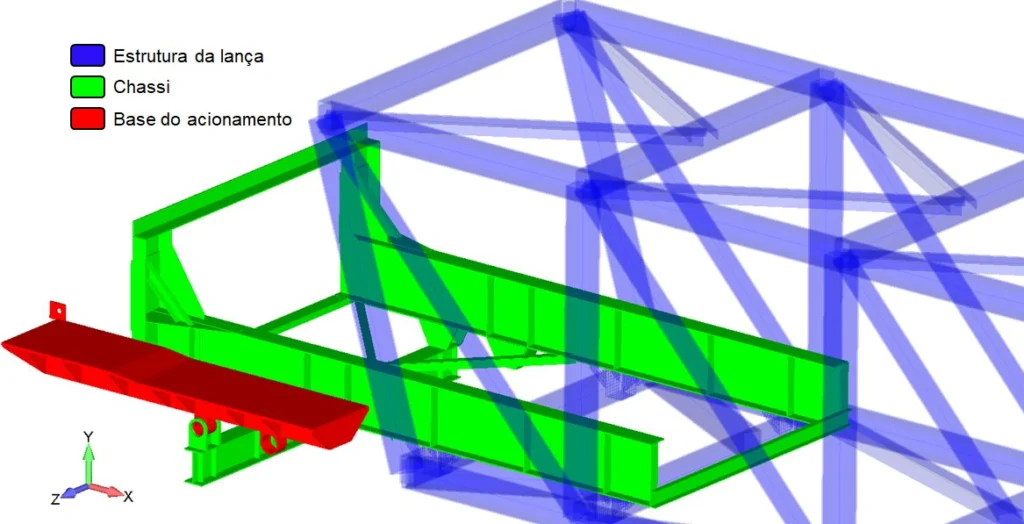
Figure 1 – Identification of the structures analyzed in the model.
The model takes into account the system’s main subsystems, including the drive base, chassis, axle, and associated components. Structural elements such as plates, beams, and connections are represented in a way that accurately captures the overall stiffness of the assembly, as shown in Figure 2.
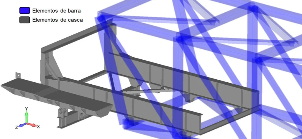
Figure 2 – Identification of the elements used in the model.
Furthermore, critical rotating components, such as the drive drum shaft, are modeled in greater detail, allowing for an assessment of their behavior under combined loads, as shown in Figure 3.
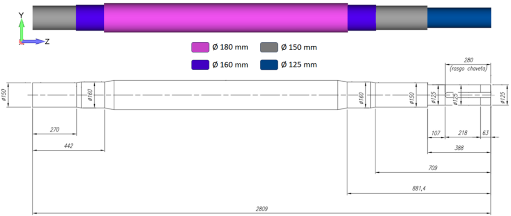
Figure 3 – Model of the drive drum shaft.
Field Measurements and Vibration Analysis
To ensure the reliability of the models and understand the system’s actual behavior, field measurements were conducted. These measurements included dimensional surveys and the acquisition of vibration data using accelerometers and a high-speed camera for dynamic analysis, as well as non-destructive testing methods such as ultrasonic testing and penetrant testing to verify Structural Integrity, as shown in Figure 4.
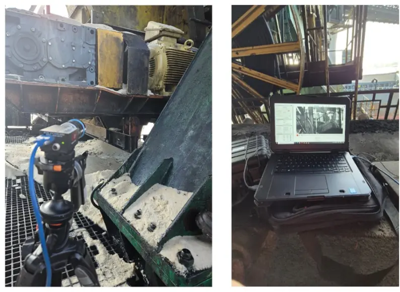
Figure 4 – Equipment used to measure vibration.
Analysis of signals in the time and frequency domains makes it possible to identify characteristic failure patterns, such as imbalance, misalignment, or external excitations. In many cases, vibration peaks associated with the system’s rotation are observed, as illustrated in Figure 5.
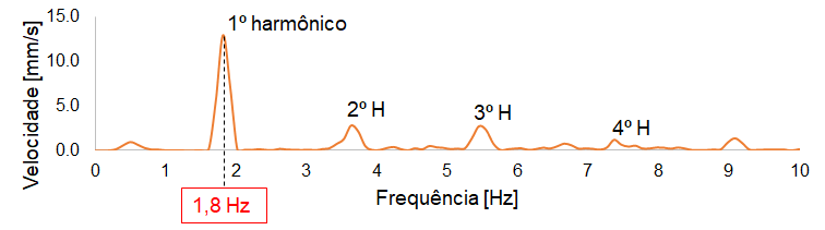
Figure 5 – Vibration velocity in the frequency domain.
Similarly, different points on the structure are monitored to determine how vibrations propagate, making it possible to identify regions that are more susceptible to dynamic amplification, as shown in Figure 6.
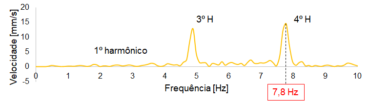
Figure 6 – Vibration frequency measured on the chassis.
Structural Analysis and Code Compliance Verification
Subsequently, based on the models developed, structural analyses are performed considering different operational scenarios, such as steady-state conditions and initial transient conditions. The results allow for the evaluation of stress levels and utilization factors of the structural members, in accordance with the criteria established by technical standards, such as NBR 8800, as shown in Figure 7.
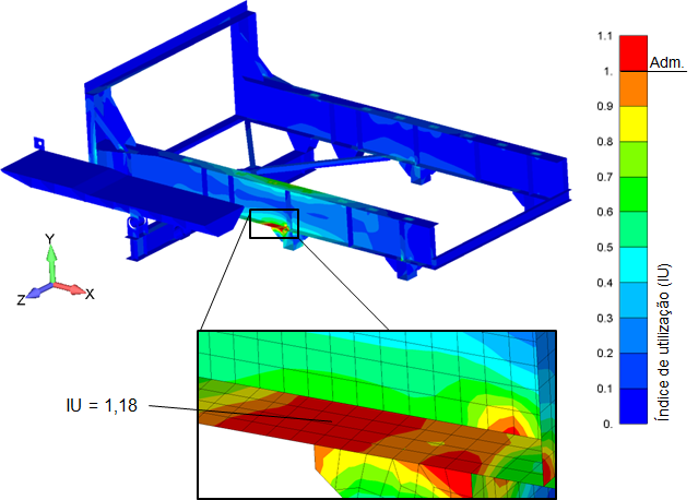
Figure 7 – Utilization rates in structural elements.
In addition, structural joints are evaluated to ensure that welded and bolted connections meet strength and safety requirements.
Modal Analysis and Resonance Phenomena
Modal analysis is a fundamental step in understanding the dynamic behavior of a structure. It is used to determine the system’s natural frequencies and vibration modes. When these frequencies coincide with excitation frequencies, resonance can occur, resulting in a significant amplification of the vibrations, as illustrated in Figure 8.
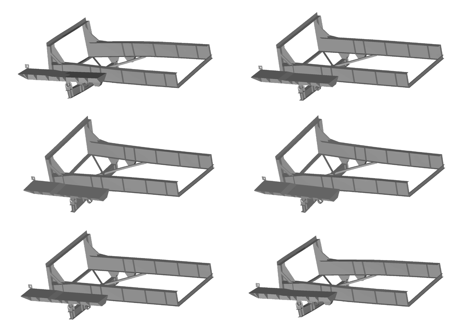
Figure 8 – Natural vibration mode of the structure.
Identifying this type of behavior is essential for implementing corrective actions, such as adjusting structural stiffness or modifying operating conditions.
Diagnosis of Mechanical Failures
The integration of field measurements and numerical analyses makes it possible to identify the root causes of vibrations. One of the mechanisms frequently observed is the imbalance of rotating components, which may be associated with permanent deformations or severe operating conditions, as illustrated in Figure 9.
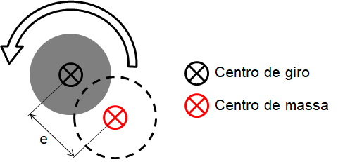
Figure 9 – Illustration of shaft imbalance.
Consequently, this type of failure can place additional stress on the bearings and the support structure, exacerbating the problem over time. Furthermore, conditions such as high-torque operation and material buildup contribute to the worsening of the situation.
Proposal for Structural Solutions
Based on the diagnosis, technical solutions were proposed to mitigate vibrations and increase the system’s reliability. Among the main strategies, Structural Reinforcement critical areas stands out, with the aim of increasing stiffness and improving stress distribution, as shown in Figure 10.
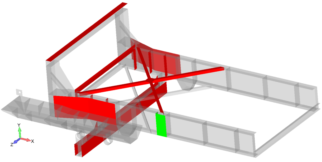
Figure 10 – Proposed structural reinforcements.
These interventions were designed to meet regulatory criteria and ensure adequate performance under various operating conditions. Details of the solutions can be seen in Figure 11.
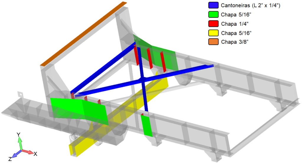
Figure 11 – Details of the structural reinforcements.
Finally, additional measures were recommended, such as replacing components, making operational adjustments, and improving auxiliary systems.
As a result, implementing the proposed solutions is likely to lead to a significant reduction in vibration levels, an improvement in structural conditions, and an increase in the service life of the components.
Monitoring of Field Implementation
In addition to numerical analyses, validating solutions in the field is a crucial step in ensuring the effectiveness of the interventions carried out.
That said, once the structural solutions had been defined, technical oversight was provided for the installation of the reinforcements in the drive system, with the aim of ensuring that the work performed complied with the design guidelines and best engineering practices.
In this context, during this phase, aspects related to the assembly, welding, and inspection of structural components were evaluated, in addition to the operating conditions observed in the field. This approach made it possible to ensure the quality of the work and the integrity of the interventions carried out.
The regions where structural reinforcements were installed are shown in Figure 12, highlighting the critical points previously identified in the analyses.
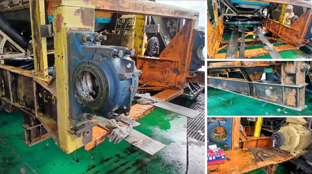
Figure 12 – Overview of the areas where structural reinforcements were installed.
Subsequently, during the monitoring process, isolated nonconformities related to construction practices were identified, including inadequate storage conditions for welding consumables and the need for adjustments during assembly. These issues were properly addressed on-site and did not compromise the final quality of the structures following corrective inspections.
To verify the integrity of the welds, non-destructive tests were performed, notably the penetrant testing shown in Figure 13, which made it possible to identify surface discontinuities in the inspected areas.
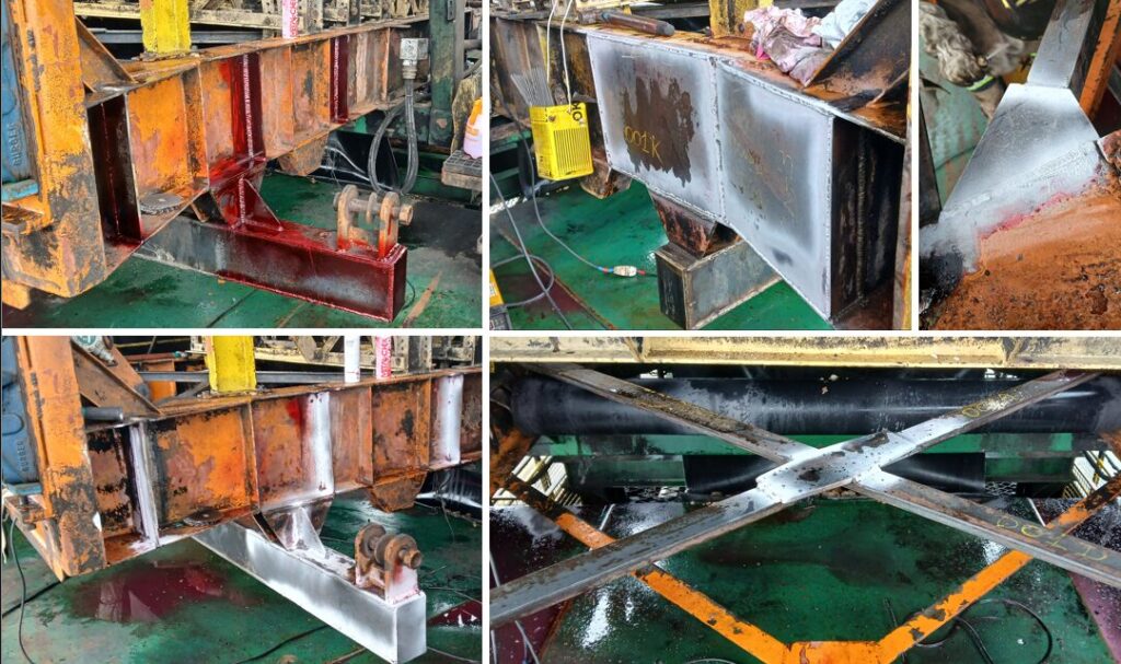
Figure 13 – Penetrant testing.
In addition, ultrasonic tests were conducted, as shown in Figure 14, to evaluate internal discontinuities and verify the volumetric quality of the welds.
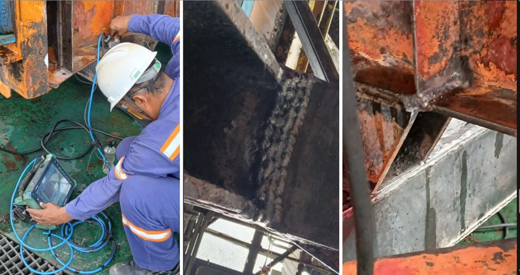
Figure 14 – Ultrasonic testing.
The nonconformities identified during the inspection process were properly addressed and reevaluated, ensuring compliance with the applicable technical criteria and guaranteeing the reliability of the work performed.
Conclusion
In short, an integrated analysis of drive systems—combining structural modeling, field measurements, and regulatory assessments—is essential for the accurate diagnosis of vibration-related problems.
In fact, studies show that properly identifying root causes makes it possible to propose effective solutions capable of restoring Structural Integrity ensuring the safe operation of equipment.
The experience we have gained from projects of this nature highlights the importance of having specialized teams and proven methodologies to address complex challenges in industrial engineering.
Contact Kot Engenharia
Join our more than 150 customers, contact our team and find out how we can assist you with structural and dynamic analyses.
Since 1993, we have specialized in developing engineering solutions through inspections, technical testing, and the use of computational methods to evaluate steel structures and industrial equipment.
Be sure to follow our pages on LinkedIn, Facebook and Instagram and keep following our content.
FAQ
1. What are the main risks associated with excessive vibration in industrial conveyor drives?
Severe vibration in drive assemblies (motors, gearboxes, and shafts) causes accelerated material fatigue, loosening of bolted connections, cracks in weld beads, and premature wear of bearings and gears. In extreme cases, these dynamic stresses can cause catastrophic failure of the structural base, resulting in costly unscheduled downtime and endangering the physical safety of operators.
2. How does the Finite Element Method (FEM) help in diagnosing vibrations?
FEM allows engineers to build a highly detailed three-dimensional mathematical model of the entire drivetrain structure (chassis, axles, plates, and supports). Using this model, engineers can simulate dynamic and static behavior under various operating conditions (such as startup and steady state), accurately identifying the areas that experience the highest stress concentrations and where stiffness needs to be increased.
3. What is modal analysis, and why is it important for preventing resonance?
Modal analysis is the numerical study used to determine the natural frequencies and vibration modes of a structure. It is essential because, if the rotational frequency of a motor or shaft (excitation frequency) is very close to one of the structure’s natural frequencies, resonance occurs. This phenomenon dramatically amplifies the amplitude of the vibrations, even if the applied force is small.
4. What is the role of field measurements in the validation of computational models?
Field measurements (using accelerometers, high-speed cameras, and sensors) collect actual vibration data from the equipment in operation. This vibration frequency and velocity data is compared with the responses from the three-dimensional (FEM) model. This calibration process ensures that the computer simulations accurately represent the machine’s actual physical behavior before any structural changes are proposed.
5. What structural solutions are used to mitigate vibration in these systems?
The main strategy involves the development of structural reinforcements (such as the addition of bracing, stiffeners, and modifications to metal profiles). The goal is to modify the overall stiffness of the drive base to “shift” its natural frequencies away from the operating frequencies of the rotating components, thereby eliminating resonance and better distributing stresses at the connections in accordance with standards such as NBR 8800.
6. Why are ultrasonic (US) and penetrant (LP) tests performed after field repairs?
After the physical installation of the designed reinforcements, it is vital to ensure that the new welds are free of defects. Penetrant testing (PT) is a fast and highly sensitive method for detecting surface-opening discontinuities (such as surface cracks and porosity). Ultrasonic (US) testing, on the other hand, evaluates the interior of the weld bead, identifying internal volumetric defects (such as lack of fusion or slag inclusions), thereby ensuring the complete reliability of the repair work.