
The CFD (Computational Fluid Dynamics) simulation applied to the design of the BOTO urban hybrid prototype resulted in a drag coefficient (Cd) of 0.20. Using a 3D scanning methodology for scaled-down models, the study identified critical points of flow separation and proposed improvements to the rear fairing. The final result represents aerodynamic efficiency significantly superior to that of typical compact cars, such as the Fiat 500 (Cdof 0.33 to 0.36), optimizing the range and performance of the electric/human-powered vehicle.
Want to understand how this optimization was carried out in practice and see the BOTO’s aerodynamic pressure maps? Keep reading the article below!
Introduction
The use of compact vehicles has become increasingly attractive in large urban centers. In this context, CFD simulation analysis contributes to the development of solutions focused on urban mobility. Furthermore, the greater ease of maneuvering and parking smaller vehicles represents an opportunity for companies in the sector.
In addition to their ease of maneuvering in traffic, the type of propulsion used in these vehicles is also a distinguishing feature. Some models use hybrid propulsion via pedals with electric assistance, similar to e-bikes. However, these vehicles feature fairings and offer greater comfort to the user.
One of the main obstacles to the wider use of bicycles in large cities is, above all, exposure to the elements. Rain, wind, pollution, and even mud puddles can sometimes make the daily commute to work impractical.
In this regard, streamlined vehicles have been gaining prominence, especially in more developed countries such as Germany. The TWIKE, for example, is a well-established initiative in this segment.
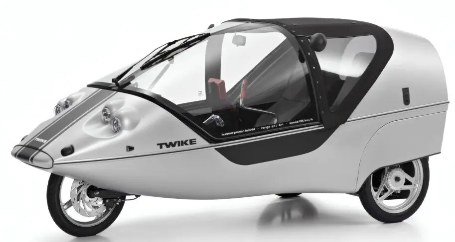
Figure 1 – TWIKE hybrid vehicle powered by human and electric propulsion.
In Brazil, a company based in São Paulo has developed a vehicle called BOTO, with organic shapes inspired by the mammal of the same name, which is very common in the tropics.
To develop the BOTO prototype, Kot conducted simulations using CFD to evaluate improvements aimed at reducing aerodynamic drag. Given the limited power of human propulsion supplemented by an electric motor, any reduction in drag has a positive impact on the vehicle’s performance, both in terms of speed and range.
Modeling
Since the vehicle is in the early stages of development, a scaled-down model was used to create the finite-volume mesh. The scaled-down model was then scanned, allowing it to be quickly imported into the CFD software. As a result, time-consuming steps in the process, such as detailed modeling, were significantly reduced.
The use of scanned models has some limitations in terms of accuracy. However, in analyses conducted during the early stages of prototyping, the speed of iterations is often more important than the absolute accuracy of the results.
This is because the prototype undergoes constant changes during development. As a result, testing new solutions and improvements becomes a frequent occurrence, as does the need to quantify small performance gains.
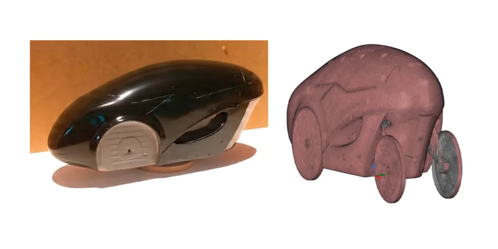
Figure 2 – Modeling using the digital scanning technique for scaled-down models.
Subsequently, the model underwent minor adjustments before being integrated directly into the CFD software. Scale adjustments were made to reflect the actual dimensions, and corrections were applied to areas with imperfections resulting from the scanning process.
Results
The simulation results therefore indicated the need for improvements to the upper rear section of the prototype. The goal was to shift the point of flow separation while keeping the flow closer to the surface. As a result, total drag was reduced.
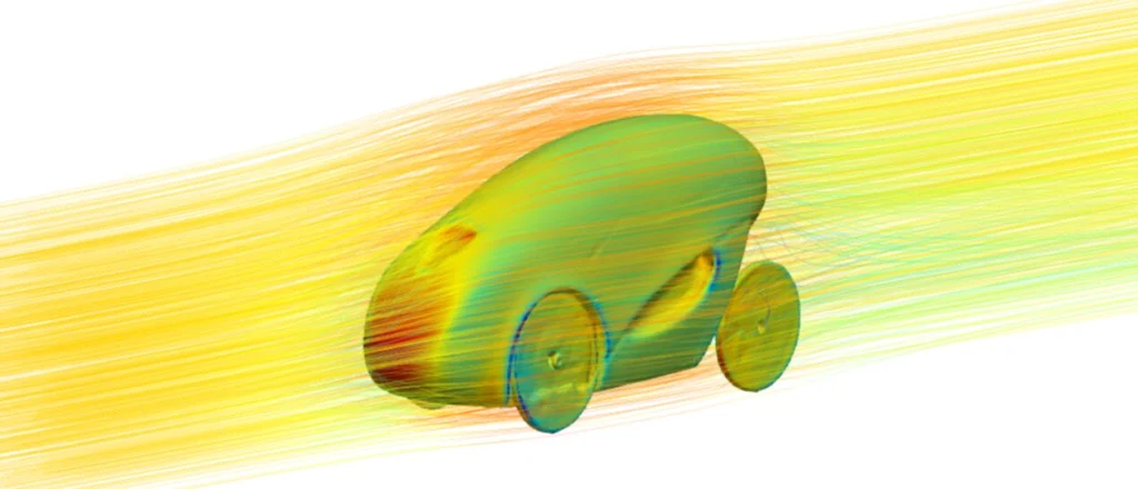
Figure 3 – Results – Pressure distribution on the fairing of the BOTO prototype.
Since this is a boxy body without aerodynamic profiling, the drag coefficient (Cd) calculated by CFD was on the order of 0.20. For comparison, several traditional compact vehicles sold in Brazil can be considered.
The Fiat 500, for example, has a drag coefficient between 0.33 and 0.36. The GM Kadett, on the other hand, known for its low aerodynamic drag, achieved a drag coefficient of approximately 0.30 in its best versions.
In contrast, bicycles without any type of fairing have drag coefficients ranging from 1.1 to 0.88. Therefore, there is a significant difference compared to the proposed vehicle.
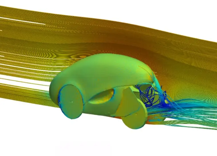
Figure 4 – Results – addition of a fairing near the rear wheel of the prototype.
Final considerations
The proposed improvements were quickly implemented using the scanning technique. This made it possible to quickly evaluate the changes made to the scale model.
Based on CFD flow analyses, it became possible to propose improvements aimed at reducing aerodynamic drag. Consequently, vehicle performance improved, contributing to the development of alternatives for urban mobility.
Contact Kot Engenharia
Are you experiencing problems with premature failures in the mechanical components of your vehicle, fleet, or equipment? For example, issues such as unexpected breakdowns, accelerated wear, or fatigue failures can compromise safety and result in high maintenance costs.
In this case, proper technical analysis makes it possible to identify the root causes of the failure, preventing recurrences and helping to increase the reliability of mechanical systems. Join our more than 150 customers, contact our team and learn about our services.
Since 1993, we have been specialists in developing engineering solutions through inspections, technological tests, and the use of computational methods for complex assessments of concrete and metal structures and industrial equipment.
Be sure to follow our pages on LinkedIn, Facebook and Instagram and keep following our content.
FAQ
1. What is CFD simulation, and how is it used in vehicle development?
CFD (Computational Fluid Dynamics ) simulation is a computational technology used to simulate the behavior of moving gases and liquids and their interaction with solid surfaces. In vehicle development, it replaces or complements costly wind tunnel tests, allowing for the digital mapping of streamlines, areas of turbulence, and drag forces acting on the bodywork of a moving vehicle.
2. How is a vehicle's drag coefficient ($C_d$) calculated?
The drag coefficient (Cd) is a dimensionless quantity that quantifies the aerodynamic drag of an object. It is calculated as the ratio of the drag force (Fd)—measured in a simulation or test—to the fluid density (p), the vehicle’s speed (v), and its projected frontal area (A), according to the following physical equation:
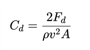
The lower this number, the more easily the vehicle cuts through the air, requiring less energy to move.
3. What are the advantages of using 3D scanning of physical models in CFD simulation?
The main advantage is the speed of iteration during the initial design stage (concept phase). Instead of spending weeks modeling complex organic surfaces from scratch in CAD (Computer-Aided Design) software, engineers can physically sculpt rapid, small-scale models, scan them in minutes, and import them directly into the finite-volume mesh of the CFD software to obtain preliminary diagnostics.
4. What are the accuracy limitations when using scanned models in CFD?
Digitally scanned models may exhibit minor surface imperfections, sensor reading noise, and millimeter-level deviations from the actual model. Although these limitations prevent absolute decimal-level precision in the final results, they are perfectly acceptable at the beginning of the design process, where the primary focus is on identifying trends in flow behavior (such as boundary layer separation points) and quantifying relative improvements among different design proposals.
5. Why is a drag coefficient of 0.20 considered excellent for the BOTO prototype?
A Cdof 0.20 places the BOTO prototype among the most aerodynamic production electric vehicles on the global market. For comparison, it is about 40% more efficient than traditional compact city cars (such as the Fiat 500, which ranges from 0.33 to 0.36) and experiences only a fraction of the drag faced by a conventional bicycle without fairings, whose Cdcan reach 1.1.
6. How does reducing aerodynamic drag affect electric or hybrid-powered urban vehicles?
In vehicles with limited power (such as hybrid systems that combine human pedaling and auxiliary electric motors), air resistance is the primary factor in energy consumption at medium and high speeds. By reducing aerodynamic drag, the power required to overcome air resistance is drastically reduced, which directly translates into higher top speed, less effort on the part of the driver, and a significant increase in electric battery range.


