")
In general, computational fluid dynamics (CFD ) is known for applying the finite volume method (FVM) to problems involving fluid flow, heat transfer, and other phenomena, based on concepts from numerical methods and thermofluid dynamics. The discrete element method (DEM), on the other hand, is applied when the goal is to analyze the displacements and rotations of discrete bodies. Before continuing, to understand the differences between the methods, check out this content in a previously published blog post. In this article, learn how Kot Engenharia both concepts in the analysis of an ore transfer system.
CFD-DEM analysis of an ore transfer system
First, a transfer chute is a component commonly found between conveyor belts that is used to direct the flow of material during the unloading process. In this context, a client company installed a new chute at its plant with the goal of reducing dust generation and emissions into the external environment. However, the new chute did not perform as expected, and Kot’s task was to identify the phenomena responsible for the generation and release of dust into the environment during the transfer of ore.
First, the behavior of the bulk material flow was analyzed using DEM in specialized software. As a result, it was concluded that there was no risk of clogging, as illustrated in Figure 1.
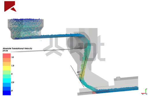
Figure 1: Material flow in the chute - SOURCE: Kot Collection.
Next, the same software was used to couple CFD and DEM, with the aim of evaluating the airflow inside the chute. This made it possible to observe the formation of vortices in the inner region and a zone of high turbulence, which increases dust generation. These results are shown in Figure 2.
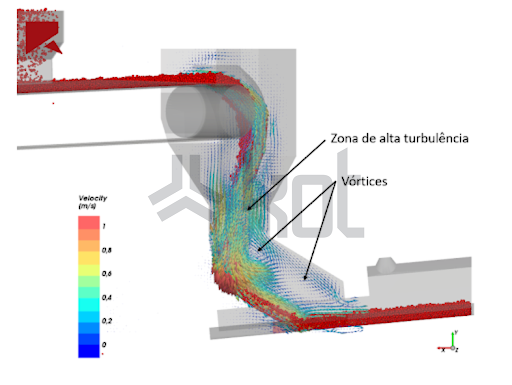
Figure 2: Air flow during kick discharge - SOURCE: Kot Collection.
In addition, to gain a more detailed understanding of the observed phenomenon, a study of the airflow in the material receiving conveyor was conducted. In this case, the conveyor has its own dust control system, which connects to the belt cover, which serves the same function. To this end, the analysis was performed using a computational fluid dynamics tool based on the FVM.
The results showed that the dust control system effectively fulfills its purpose. However, in the transition zone between the system and the conventional belt cover, factors conducive to dust generation were observed, since there is no enclosure. Vortex formation can be seen in Figure 3. On the other hand, at the outlet of the cover, it is evident that the phenomenon is mitigated.
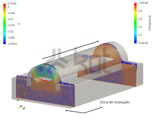
Figure 3: Cross-sections at the roof inlet and outlet - airflow pressures (P) and velocities (U) - SOURCE: Kot Collection.
In addition, the regions of turbulence along the conveyor’s covered area were analyzed, as shown in Figure 4, where the lines represent the airflow. Thus, it is evident, once again, that the transition region is the most critical point in terms of air currents.
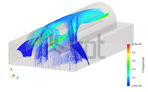
Figure 4: Air flow in the roof area - SOURCE: Kot Collection.
Consequently, the chute and the transition area between the dust control system and the cover are responsible for the high levels of dust generation and leakage. Based on the results, Kot Engenharia the causes of these problems and developed solutions, which involve geometric modifications to optimize the flow and methods to improve air recirculation.
Kot Engenharia has the experience and resources necessary to carry out simulations involving DEM and CFD analysis, such as the case described in this article. Contact our team for more information!
Follow our pages on LinkedIn, Facebook e Instagram to keep up with our content.


