
Kot carried out a structural assessment of conveyors in a maritime terminal. To do this, we carried out a static analysis of the components and their connections in accordance with the applicable standards and requirements. Read this article to find out more about this Succes story developed by the company's team!
You can read more success stories from Kot Engenharia clicking here!
Introduction
First, conveyors—more commonly known as TRs in the field of engineering—are widely used for transporting various types of solid and granular materials. Their applications can meet a variety of needs.
To that end, Kot conducted a study aimed at performing a structural assessment of these assets through static and connection analyses. Figure 1 provides an overview of these structures.
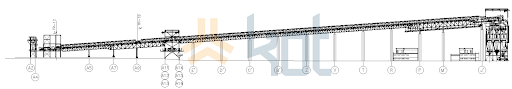
Figure 1: General view of the structures. [1]
In addition, to prevent contamination of the sea caused by falling materials, containment structures were designed for the conveyors. The structural analysis took into account the additional load caused by these structures.
Structure modeling
First, the initial step was to model the conveyor using beam-column elements with the aid of the finite element analysis software finite element methodPROCAL , developed by the company, to determine the acting forces and stresses, thereby enabling structural analysis in accordance with applicable standards.
Subsequently, to aid in visualizing the computational model, a 3D structural model was also generated using the VRML programming language, as shown in Figure 2.
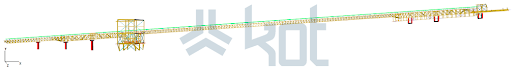
Figure 2: 3D structural model - VRML. [1]
Definition of loads
Next, the loads applicable to the structural analysis were defined based on the recommendations of ASCE 7-05 [2] and NBR 8800:2008 [3]. Some of the loads considered were:
-
- Own weight;
-
- Material loading;
-
- Tension in the belt;
-
- Overloading of roofs, walkways, platforms and stairs;
-
- Wind load;
-
- Chute clogging.
In addition, the criteria used to evaluate the rebar used in the structure are presented below:
-
- Utilization index: Evaluates the degree of stress to which a structural element is being subjected. It is determined from the ratio between the stress acting on each bar and the admissible resistance determined by the standard for steel structures;
-
- Permissible use index: This is the value defined by a standard, used as a reference for approving or disapproving the degree of stress of a structural element.
Finally, the allowable utilization ratio for bar members, for all loads considered, is 1.
Link analysis
Connecting elements enable parts of the structure to be joined to each other or to external elements. Welds, screws, threaded rods and bolts are the main means of connection.
In addition, all connections are commonly classified according to their rigidity—that is, their ability to prevent relative rotation of the connected parts. There are two possible categories based on this criterion:
-
- Flexible connection: No resistance to bending moments. In this case, only normal and shear forces are transmitted;
-
- Rigid connection: Characterized by the total restriction of bending moments. There is no considerable relative rotation after the load is applied.
Therefore, these connections must be designed so that their design strength is equal to or greater than the load on the connection, withstanding all applied forces and meeting all the requirements set forth in NBR 8800: 2008 [3].
Accordingly, the criteria used to verify the links in question are listed below:
-
- Utilization index: Representsthe degree of stress to which the connection is being subjected. The connection is approved when its utilization index is less than 1.
Results
Subsequently, a static analysis of the conveyor structure was performed to determine the impact of installing the material containment trough. Accordingly, three distinct cases were considered, as detailed below.
-
- 1st - Material clogging: The utilization rates obtained from this structure check are shown in Figure 3.
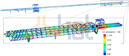
Figure 3: Result of static analysis in case of clogging. [1]
As can be seen in the figure, some elements failed the analysis.
2nd - Boundary Condition: The aim of this analysis is to determine the boundary condition of the structure, i.e. what is the maximum load of material that can be allowed in the containment channel. The result can be seen in Figure 4.
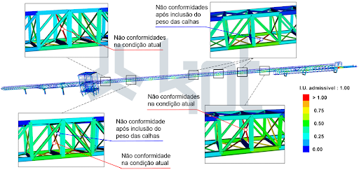
Figure 4: Result of static analysis in borderline case. [1]
It was therefore concluded that the structure was not ready for the installation of the gutters and reinforcements are needed.
3rd - Normal gutter operation: The aim of the analysis is to survey the elements that need to be reinforced in the structure so that the gutter can be installed. Figure 5 shows the results obtained in this last stage.
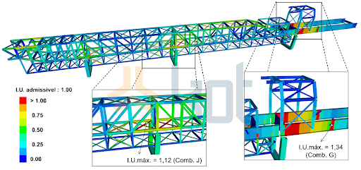
Figure 5: Result of the static analysis - Utilization rates. [1]
Finally, the static analysis and connection analysis revealed that the structure was not suitable for the installation of material containment chutes without prior modifications. Consequently, Kot recommended several necessary actions to ensure the Structural Integrity assets.
Conclusion
In short, although the material containment solution was of great value from an environmental standpoint, the structural assessment served to mitigate the risk of structural collapse by proposing improvements that needed to be addressed before implementing this containment system.
In addition, it is worth noting that Kot has extensive expertise in this field, having designed hundreds of conveyors, and is able to assess different operating contexts and contribute to its clients’ results. Contact our team for more information!
Follow our pages on LinkedIn, Facebook e Instagram to keep up with our content.
References
[1] Kot Collection.
[2] AISC 2005 - Specification for Structural Steel Buildings, Allowable Stress Design and Plastic Design, July 2006, American Institute of Steel Construction.
[3] ABNT, NBR 8800, Design of steel structures and steel-concrete composite structures for buildings, 2008;


