To perform analyses of machine structures, buildings, and conveyors using the Finite Element Method (FEM), the professional in charge must evaluate the regulatory criteria relevant to the problem and the behavior of the computational model. Furthermore, this procedure is important to ensure that the evaluation conducted by the professional accurately reflects the structure’s actual behavior. Previously, one of Kot’s directors, Rafael Brasil, posted an article on the company’s blog introducing the FEM. A quick read might refresh your memory on some important details about the method! Click here to check it out.
This text presents the report of one of the engineers responsible for the Structural Assessment of Conveyors, described in the article: Succes story: Structural Assessment of Conveyors – Part 1. Here we will present the impacts that could have been generated in the result of a structural analysis if the boundary conditions had been assumed incorrectly.
Introduction
As shown in the initial analysis of the conveyor, this equipment is used to transport bulk materials. This transportation is carried out by a conveyor belt, similar to a conveyor belt. Figure 1 shows an example of a conveyor belt.
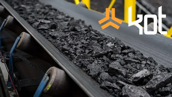
Figure 1: Conveyor belt. [1]
In order for the belt to be capable of conveying any solid material, it must be sufficiently tensioned. As a result, this tension places high stresses on the structures, causing deflections in the direction of the belt.
Evaluated boundary condition
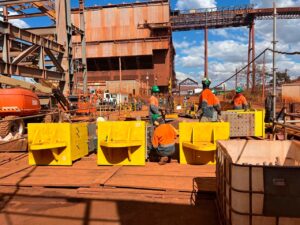
When starting the study, the Kot team quickly noticed the first point of concern in the support devices of the marine terminal transporter.
In fact, pins are the most common connecting elements found in machines and structures. In this case, it would have taken only a moment’s inattention to mistakenly assume that the connection on this conveyor behaves like a pinned joint—that is, it restricts all degrees of freedom except rotation around its Z-axis.
However, when the team responsible was studying the case, they realized that this device is made up of two rollers that allow it to move in an X direction.
For example, to better illustrate the consequences of an incorrect structural analysis, a comparison of the results for each of the boundary conditions mentioned above is presented below.
Results
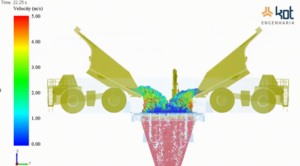
As a result, an incorrect analysis of the support elements would have led to the structure being rejected, since it would be considered that a pin-type device causes an increase in stresses in the conveyor’s support regions, as shown in Figure 2.
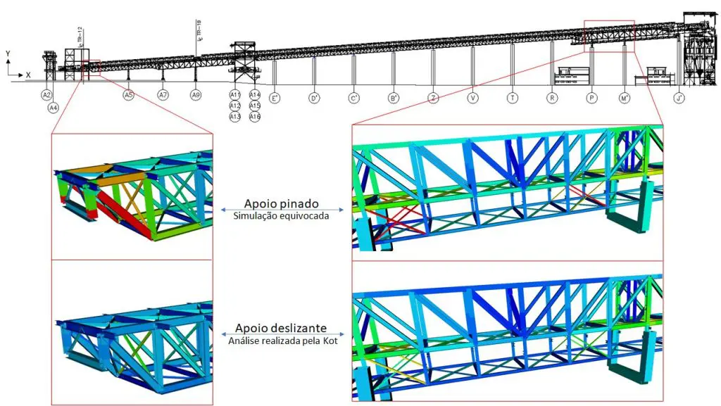
Figure 2 - Comparison between analyses. [2]
Discussion of results
On the other hand, it was found that the company that designed this structure made a sound decision in using a sliding support. This is because allowing the rollers to move freely not only reduces the stress on the metal structure but also prevents shear forces in the longitudinal direction of the conveyor from being transmitted to the supports.
Furthermore, it is reported that these sliding devices rest on isolated reinforced concrete columns that reach heights of nearly 30 meters. Shear forces at the top of these columns, even if of low magnitude, would cause high bending moments at the bases of these columns.
In this sense, it can be concluded that the design decisions significantly reduced the cost of incorporating this equipment, when comparing the two situations analyzed.
However, from the point of view of using the structure, the design is flawed, since the absence of horizontal restraint in practically all the conveyor trusses causes high displacements, reaching 4.0 centimeters during belt stretching and 6.7 centimeters in cases where the structure is set back due to temperatures of around 20°C.
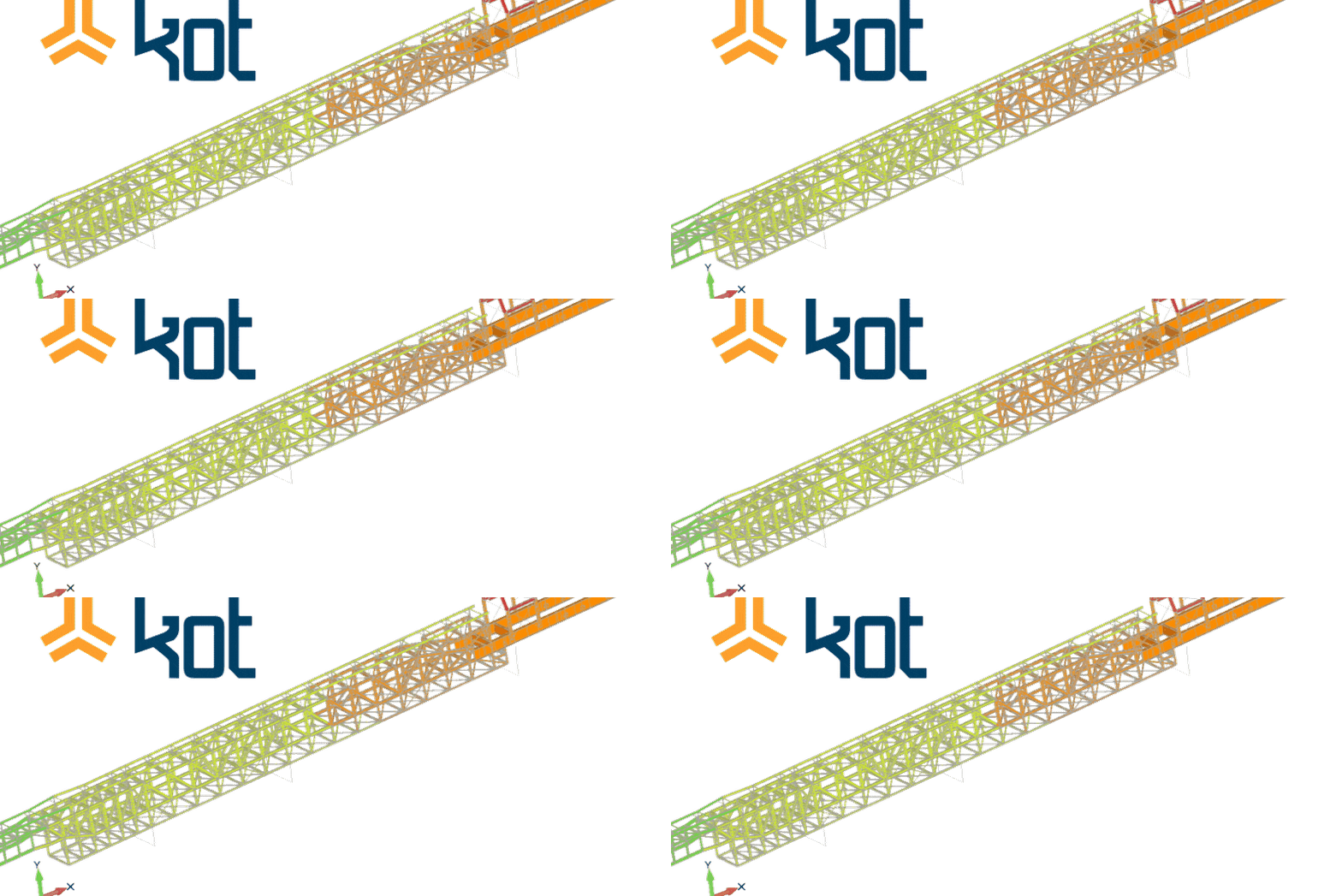
Figure 3, in turn, shows the longitudinal displacement of the conveyor during belt tensioning.
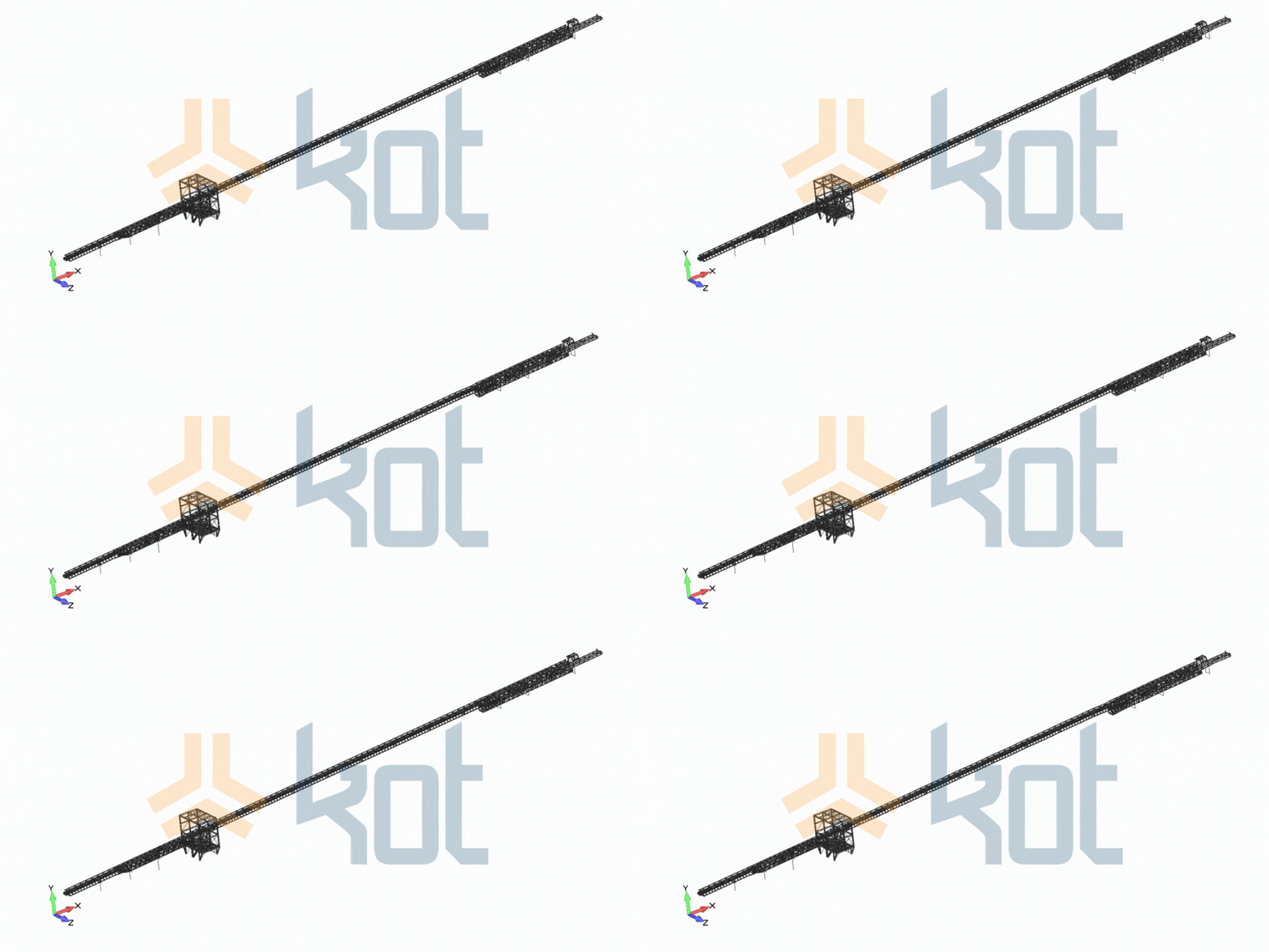
Figure 3: Shrinkage of the structure during belt stretching. [2]
Similarly, Figure 4 shows the same situation on a reduced scale, highlighting some of the structure’s shrinkage measurements in centimeters.
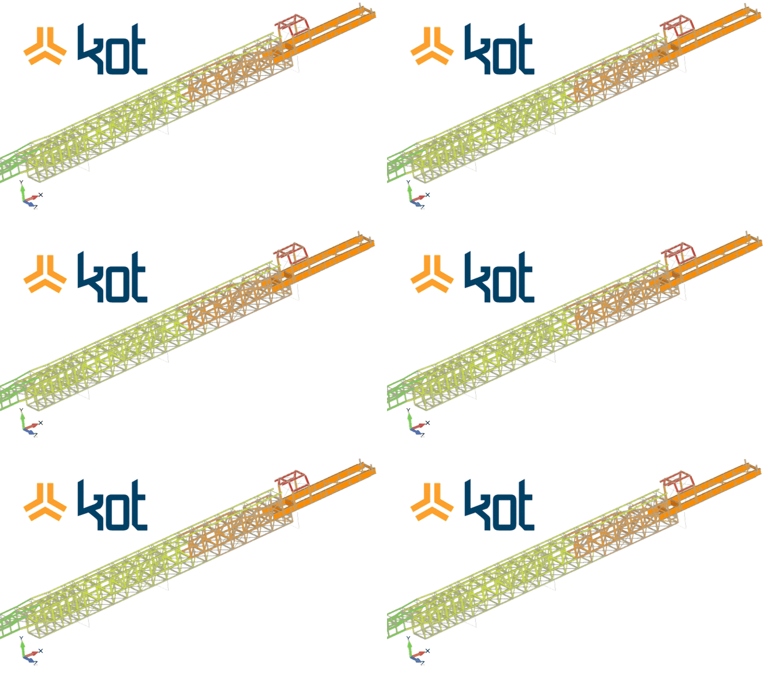
Figure 4: Focus on structure shrinkage for belt shrinkage condition. [2]
Conclusion
In short, it was observed that a misinterpretation of a structure’s boundary conditions can influence the numerical results.
In this sense, it is always important that the professional responsible for analyzing a structure uses critical thinking to interpret the data from a computational model. Kot Engenharia a team of qualified professionals with extensive know-how in the field of structural analysis, who are prepared to ensure the Structural Integrity our clients' buildings and machinery. Consult our team for more information!
Follow our pages on LinkedIn, Facebook and Instagram to continue following our content.
1. Qual a importância das condições de contorno em uma análise por Método dos Elementos Finitos (MEF)?
As condições de contorno definem como o modelo computacional interage com o ambiente externo (restrições de movimento, apoios e aplicações de carga). Se forem atribuídas de forma incorreta, os resultados numéricos de tensões e deformações não refletirão o comportamento real da estrutura, podendo levar à reprovação indevida de um bom projeto ou à aprovação de uma estrutura vulnerável.
2. Por que o esticamento da correia gera grandes esforços na estrutura do transportador?
Para movimentar grandes volumes de material a granel sem derrapagens, a correia precisa trabalhar sob alta tensão mecânica. Esse tensionamento gera forças longitudinais de elevada magnitude ao longo do caminho de rolamento, que tendem a induzir deformações, encolhimentos e desvios de alinhamento nas treliças metálicas.
3. Qual erro de interpretação poderia ter ocorrido na avaliação dos apoios do transportador?
Pela presença visual de pinos de articulação, a ligação poderia ser erroneamente classificada como um apoio pinado (que restringe todas as rotações e translações, exceto a rotação no eixo Z). No entanto, a análise detalhada de campo revelou que o dispositivo era composto por dois rolos, caracterizando um apoio deslizante com liberdade de translação no sentido longitudinal (eixo X).
4. Quais seriam os impactos de considerar incorretamente os apoios como fixos/pinados?
Se o apoio fosse modelado como pinado:
-
A simulação indicaria um pico irreal de tensões sobre a estrutura metálica nas regiões de apoio, provocando sua reprovação indevida;
-
O modelo acusaria a transmissão de esforços cortantes para o topo dos pilares de sustentação em concreto armado (que possuem quase 30 metros de altura). Mesmo pequenos esforços cortantes nessa altura gerariam momentos fletores críticos na base desses pilares.
5. Quais vantagens o projeto original obteve ao adotar apoios deslizantes?
A utilização de apoios deslizantes com rolos permitiu a acomodação dos movimentos longitudinais da estrutura, impedindo a transferência de esforços cortantes para os pilares de sustentação e reduzindo drasticamente os níveis de tensão nas treliças. Essa decisão reduziu de forma expressiva o custo global de implantação do equipamento.
6. Quais deficiências operacionais foram identificadas no estudo de deslocamentos?
Embora eficiente sob o ponto de vista de alívio de tensões, a falta de restrição horizontal em trecho significativo das treliças causa deslocamentos longitudinais expressivos:
-
Encolhimento de 4,0 cm durante o processo de tensionamento da correia;
-
Deslocamento de 6,7 cm em cenários de contração térmica da estrutura devido a quedas de temperatura de 20°C.
7. Qual é a principal lição do estudo para projetos de engenharia estrutural?
O estudo evidencia que o software de elementos finitos é uma ferramenta de cálculo, mas a validação final exige o senso crítico do engenheiro. A inspeção visual detalhada dos mecanismos físicos e a correta transposição da realidade operacional para o ambiente virtual são indispensáveis para garantir a segurança operacional e a economia do projeto.
References
[1] Abecom, (S.I). Available at: https://www.abecom.com.br/o-que-e-correia-transportadora/ - Accessed on 31/07/21, at 11:00.
[2] Kot Engenharia Collection.