
Introduction
Currently, structural analysis using finite element method (FEM) It is a widely used tool in the structural and mechanical analysis of industrial assets. For example, this assessment can be applied to yard machinery to check for non-conformities, potential failures, or even unknown phenomena.
Structural analysis
Kot has carried out the structural validation of a homogenizing reclaimer using the finite element method (FEM). The iron ore reclaimer, which has a design capacity of 1950 tons per hour, is of the overhead crane type and has two bucket wheels for reclaiming material.
Structural verification began with the creation of a finite element model of the machine in CAE (Computer Aided Engineering) software, accurately reproducing the geometry of the asset. The model generated can be seen below in Figure 1, showing the components of the equipment in different colors.
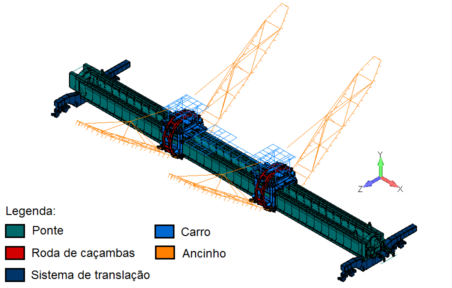
Figure 1: Finite element model of the reclaimer. SOURCE: Kot Collection.
In this model, profiled components are represented as bar elements, while those formed by plates are represented as shell elements, as shown in Figure 2 below.
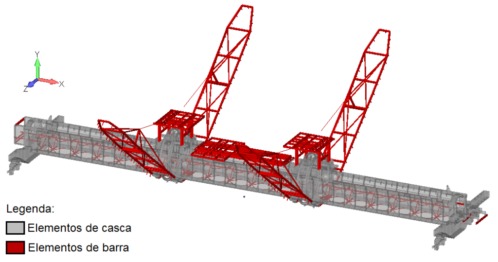
Figure 2: Bar and shell elements in the reclaimer model. SOURCE: Kot Collection.
When in operation, yard machines are subjected to high loads resulting from the equipment’s own weight, the load of material on the belt conveyor, wind loads, and contact loads, among others. Therefore, once the model has been generated, the loads acting on the structure are identified and grouped into load combinations.
Thus, using the MEF method, these load combinations are discretized and applied to the equipment’s structure to perform structural verification under various operating conditions, as recommended by the standard. Subsequently, static, modal, buckling, fatigue, and connection analyses were performed on the recovery unit in question, and the results were interpreted in accordance with standard criteria.
Subsequently, a static analysis of the machine was performed based on the stresses obtained from the finite element model. Allowable stresses, safety factors, and utilization factors (UFs) specific to each structural component were considered, depending on the load combinations applied and evaluated. In the analysis of the bar elements, utilization indices above the permissible limit were identified at the rear of the rake, as highlighted in region D of Figure 3 below.
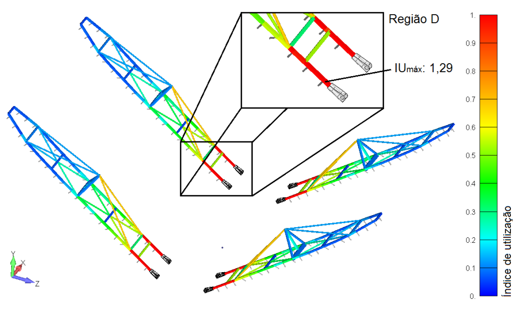
Figure 3: Bar element utilization rates in static analysis. SOURCE: Kot Collection.
Similarly, with regard to the static analysis of the shell elements, stress intensities (SI) exceeding the allowable limit are observed in the ribs of the bridge (region A in Figure 4) and in the support for the translation carriage tensioner (region D in Figure 5).
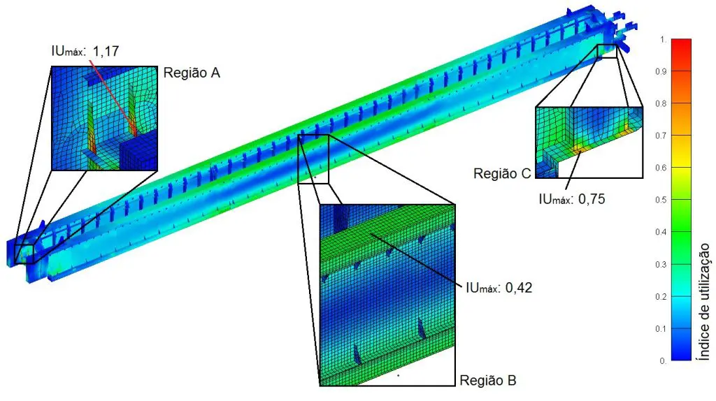
Figure 4: Bridge utilization rates in static analysis. SOURCE: Kot Collection.
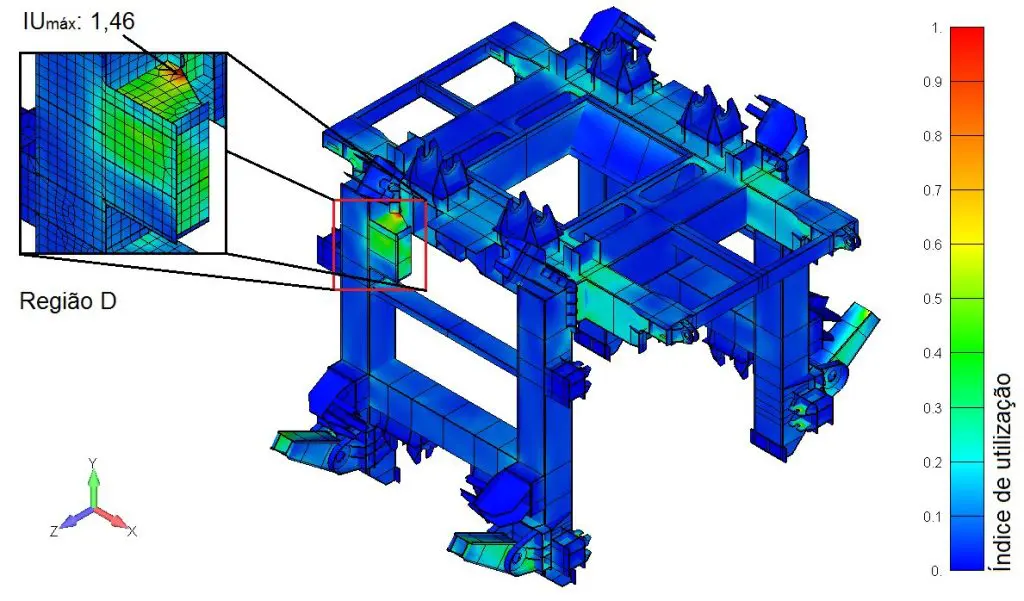
Figure 5: Stretcher support utilization rates in the static analysis. SOURCE: Kot Collection.
Subsequently, in the fatigue analysis, a normative evaluation methodology was adopted for the service life of the shell elements, which takes into account existing stress concentrators and estimates of the number of cycles, the magnitude of the stresses, and the stress variations in each element. As a result, U_i values above the allowable limit were found at the same points identified by the static analysis, as shown in Figures 6 and 7.
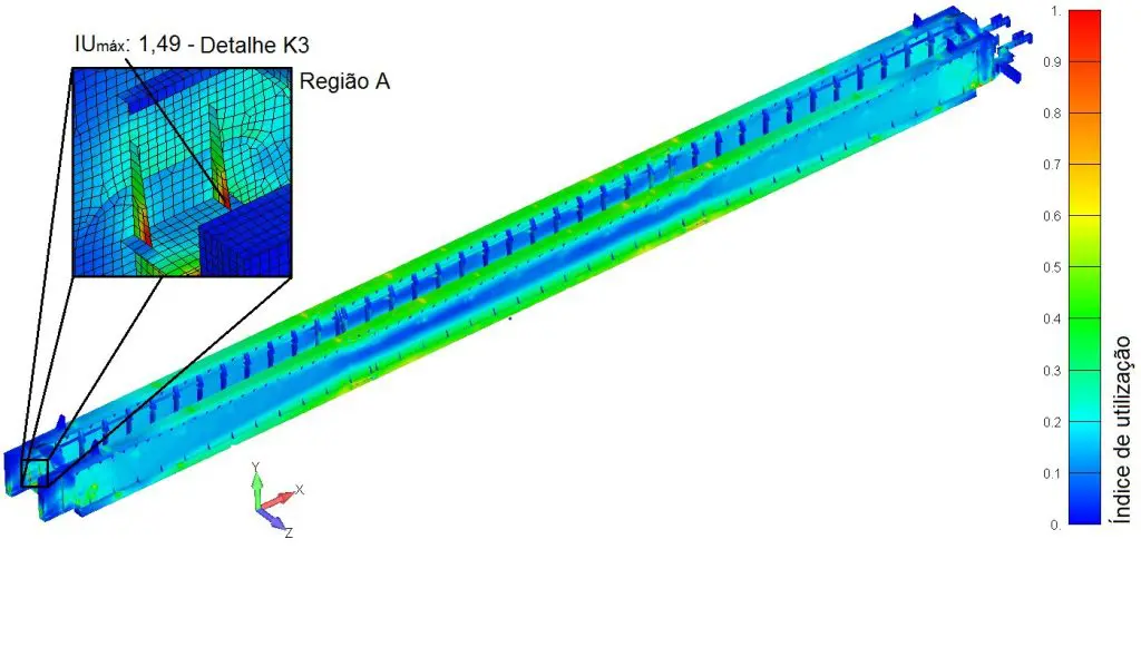
Figure 6: Bridge utilization rates in fatigue analysis. SOURCE: Kot Collection.
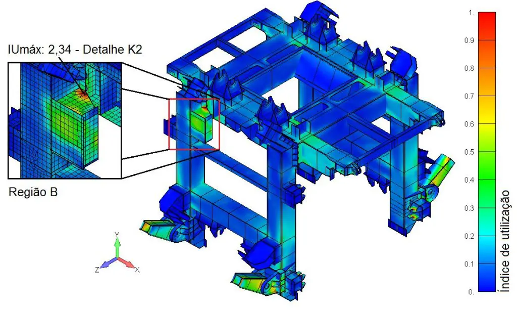
Figure 7: Stretcher support utilization rates in fatigue analysis. SOURCE: Kot Collection.
In addition, during the analysis of local buckling in slender plates subjected primarily to compression, the critical stresses were calculated. For the analysis, factors such as the type of applied stress, boundary conditions, geometric parameters, material properties, and applied stress values were taken into account, among others. The results obtained were within the allowable limits for all evaluated loading cases.
In addition, the connections, which are commonly classified according to their stiffness, were also analyzed in accordance with the standards. As a result, ultimate yields (IUs) exceeding the allowable limit were observed in the connections of some of the bridge’s tubular bracing members, due primarily to the action of operational and storm wind loads on the structure (the most critical condition for the structure). The stresses acting on the connections (for the storm wind condition) can be seen in Figure 8.
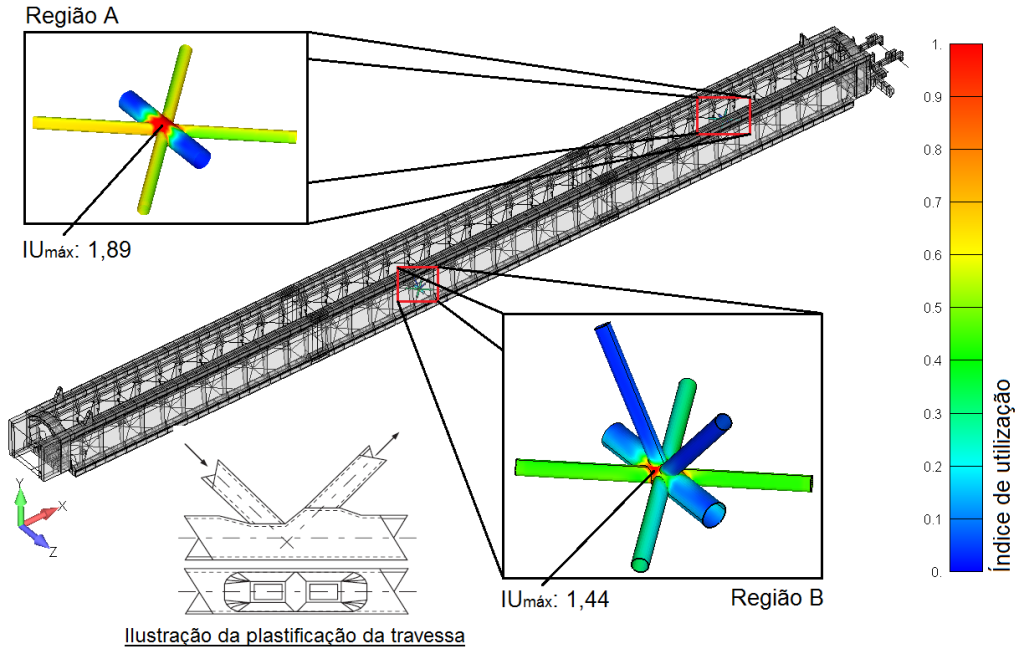
Figure 8: Structure utilization rates in connection analysis. SOURCE: Kot Collection.
In the modal analysis, the possibility of resonance of the structure was verified. The frequency of material unloading onto the impact rollers of the crane conveyor was taken as the excitation source. This identified the risk of resonance in one of the structure's natural vibration modes (Figure 9), which is characterized by the rotation of the bridge and the trolleys around the machine's longitudinal axis. As a result, it was found that the vibration speeds could exceed the limits allowed by the standard, an undesirable result for the proper functioning of the equipment.
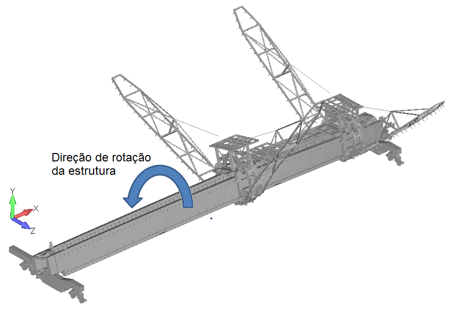
Figure 9: Evaluated natural vibration mode. SOURCE: Kot Collection.
Finally, based on the results obtained from the FEM structural analysis of the machine, some points of concern were raised. An inspection would be necessary to investigate the condition of the asset in order to determine whether or not corrective action was required.
Due to the risk of failure in the rear of the rake, in the ribs of the transverse beam supporting the bridge and in the support for the tensioner of the bucket wheel drive chain, reinforcements were proposed to bring the reclaimer's structure into line with the normative criteria, by correcting the non-conformities found.
Mechanical analysis
Mechanical analysis is used to verify the operational functioning of mechanical components, and is also relevant to the design of machinery, as systems can be dimensioned using analytical and numerical calculations.
Accordingly, Kot performed a mechanical inspection of the belt conveyor in the iron ore homogenizing recovery plant. The model used in the analysis is shown below in Figure 10.
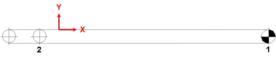
Figure 10: Model of the belt conveyor. SOURCE: Kot Collection.
Initially, during the analysis, the capacity of the conveyor in question was verified in order to assess the possibility of material spillage during its operation. Next, it was verified whether the respective belt could withstand the stresses imposed on it, based on its breaking strength. In addition, other parameters related to the belt were also evaluated at this stage, such as transition distance, vertical curves, flapping, among others.
In addition, the power required was analyzed in order to assess whether the belt conveyor's drive system is capable of meeting the design capacity, i.e. whether it has the necessary power. Also with regard to the drive system, the sizing of its mechanical components was checked, such as motors, couplings, gearboxes, brakes and backstops, based on the catalogs of the respective manufacturers and taking into account the highest power required and/or installed. In addition to the conveyor drive system, the sizing of the rollers and drum shafts was also checked.
As noted in the analysis of the overhead crane’s belt conveyor, it was observed that, during braking while carrying ore, the tension on the slack side of the drive drum is lower than the minimum allowable tension. According to the standard, this can result in the belt slipping relative to the drive drum. On the other hand, on the return roller shafts, deflection exceeding the permissible limits established by the manufacturer and by standard was observed; therefore, they were deemed non-compliant.
In addition to the belt conveyor, the bucket wheel and the travel systems of the machine, trolley and rake tipping were also analyzed. As a result, the braking moment of the machine's travel system is, in some cases, insufficient to stop it, and the travel drive wheels are unable to transmit the braking force without slipping on the rail. In addition, the mechanical service factor of the bucket wheel reducer is lower than the minimum recommended by the manufacturer. No non-conformities were identified in the trolley and rake tipping systems.
Finally, based on the results obtained from the mechanical analysis, it was recommended that the current counterweight be increased and that it be checked in the field to see if there was a rail-lock system to help with braking during storm winds. If not, it was recommended that this device be installed as a corrective measure.
Conclusion
Given the above, it is clear that using the finite element method for the structural analysis of yard machinery provides a highly reliable assessment of the asset’s structural integrity. Thus, when applying this methodology, it is necessary to know the boundary conditions, mass, and position of unmodeled components, as well as constraints and other factors. Furthermore, it is important to know the magnitude and types of stresses expected on the equipment during its service life, as well as the standards that govern each type of analysis.
Similarly, by using mechanical analysis, you can be more assertive about the operational functioning of the machines. This also extends to assessing the condition of their mechanical components and sizing their systems.
Kot has professionals who are trained to understand and evaluate the best solutions for the engineering challenges faced in the day-to-day operations of the industry, as well as for structural and mechanical analyses of yard machines. Consult our team for more information!
Follow our pages on LinkedIn, Facebook e Instagram to keep up with our content.


