
Introduction
Tunnels are fundamental structures for efficient road solutions and are widely used in regions with steep topography in order to avoid exacerbated expenditure on soil movement due to cutting and landfilling, and on construction materials in cases where the alternative is to build bridges and viaducts.
In addition, another typical use of this structure is to optimize traffic flow while ensuring safety, for example, by managing traffic at intersections. In an industrial setting, it is possible to ensure that small and medium-sized vehicles do not cross paths at grade with off-road vehicles, thereby increasing the safety and comfort of people and workers using the facility, as well as raising the average speed of traffic.
In general, there are several categories of tunnels, but corrugated tunnels stand out due to the various advantages associated with their construction method: ease and speed of execution, combined with low construction costs and the ability to use catalog-based sizing, which speeds up the design phase. For example, within this category, there are destructive (Figure 1-a) and non-destructive (Figure 1-b) construction methods, which should be chosen depending on the specific conditions of the project.
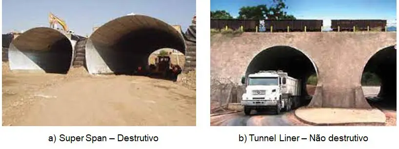
Figure 1: Examples of corrugated tunnels. SOURCE: Armco Staco®.
Problem
In this regard, Kot assisted one of its clients after determining that the operating conditions of a tunnel were inconsistent with the specifications in the catalog:
• The overburden depth above the tunnel (embankment) exceeded the maximum recommended by the manufacturer;
• The weight of vehicles traveling over the tunnel was 20 times greater than that used in the design calculations;
• The soil used in the construction of the embankment did not meet the minimum desired quality standards and exhibited high heterogeneity;
In addition, the tunnel showed signs that it was resisting in borderline conditions. Several bolts were broken and several others were in the process of advanced corrosion.
Since traffic inside the tunnel consists mainly of small and medium-sized cars, and traffic over the tunnel consists of off-road vehicles, the possibility of this structure collapsing puts the lives of users traveling there at risk, in addition to disrupting the connection between neighboring cities and interrupting the client’s business operations.
Solution
Accordingly, Kot conducted a detailed structural and geotechnical analysis using the finite element method (FEM)to verify the tunnel’s safety.
In general, this type of structure is typically designed using catalog data through an analytical approach, with clearly defined vehicle loads and embankment heights. Consequently, any change in the design assumptions requires the development of a sophisticated computational model that accounts for soil-structure interaction in the mathematical modeling of the problem.
Since the structure was missing bolts and exhibited a number of defects, these factors had to be taken into account in the analyses to issue an opinion on the tunnel’s current structural integrity (fitness for service). Damage caused by broken bolts and the reduction in the strength of the plates due to loss of thickness were factored in.
The asset's stress history was simulated, from its construction to the current situation, in order to take into account the impact of deflections on the stresses developed in the corrugated sheets.
For example, the figure below shows the bending moment diagram during the asset's construction phase.
Figure 2: Diagram of bending moments during the tunnel earthing process. SOURCE: Kot Collection.
In addition, the effects of the moving load on the tunnel were simulated using a 3D model to assess the influence of soil displacement caused by the load on the structure, taking into account the possibility of stress superposition within the rock mass. Figures 3 and 4 show, respectively, the increase in axial forces and bending moments due to the presence of the live load on the tunnel.
Figure 3: Distribution of normal stresses along the tunnel during vehicle traffic. SOURCE: Kot Collection.
Figure 4: Distribution of bending moments along the tunnel during vehicle traffic. SOURCE: Kot Collection.
Thus, based on the applied loads, it was possible to assess the structural condition of the tunnel during the structural analysis. Furthermore, the stresses developed in the backfill soil due to vehicular traffic over the tunnel were determined, as shown in Figure 5.
Figure 5: Stresses in the ground caused by the flow of vehicles through the tunnel. SOURCE: Kot Collection.
Outcome
In conclusion, following the detailed structural and geotechnical analysis conducted by Kot, it was found that the tunnel did not comply with the applicable regulatory criteria. Consequently, the analyses indicated a critical condition, suggesting a potential risk of structural collapse.
Figure 6: Distribution of bending moments along the tunnel during vehicle traffic. SOURCE: Kot Collection.
Figure 7: Stresses in the ground caused by the flow of vehicles through the tunnel. SOURCE: Kot Collection.
Consequently, the client was advised to modify the asset’s operating conditions in order to reduce the risk associated with its operations. One of the measures involved lowering the embankment above the tunnel so that the calculated stresses would be compatible with its current strength. This measure ensures the safety of everyone who passes through the area, without disrupting production line operations.
Kot has a team of professionals qualified in structural integrity and analysis, ready to develop the best engineering solutions for your business. Contact our team for more information!
Follow our pages on LinkedIn, Facebook e Instagram to keep up with our content.


