A análise estrutural de torres de transmissão de energia é indispensável para garantir o abastecimento contínuo e a segurança operacional de plantas industriais e do Sistema Interligado Nacional (SIN). Integrando inspeção visual e dimensional de campo, Modelagem por Elementos Finitos (MEF) e análise modal, essa metodologia identifica danos por corrosão e deformações plásticas, avalia o comportamento das ligações sob ventos de tormenta e direciona o projeto de reforços estruturais de alta precisão.
Entenda como a análise estrutural previne o colapso de torres de transmissão.
Introduction
Currently, Brazil has a large-scale electricity generation and transmission system, dominated by hydroelectric power plants. The National Interconnected System (SIN) is responsible for interconnecting the electrical systems through a transmission grid. Power transmission towers are fundamental components of this system, supporting the high-voltage cables that carry electricity to distribution substations in urban and industrial centers.
In addition, these transmission towers are designed to support high-voltage cables as well as lightning protection cables (over long distances) and are engineered to withstand loads such as their own weight, wind loads, and the weight of the cables in the event of a break.
In this regard, one of our clients requested a structural assessment of five power transmission towers due to signs of structural damage. Furthermore, it should be noted that the transmission lines supported by these towers are crucial to this client’s production process, as they carry power to the substation at their industrial plant. Figure 1 below shows the general layout of one of the assets in question.
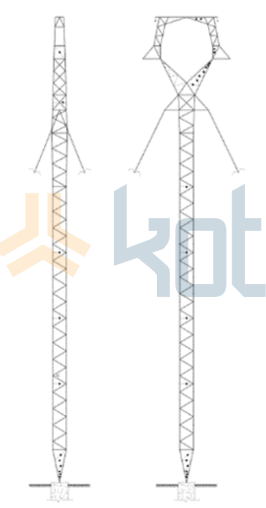
Figure 1: Transmission tower arrangement. SOURCE: Kot Collection.
In light of this, Kot proposed conducting a comprehensive assessment of Structural Integrity metal structures, from the initial field survey through to the structural evaluation, including recommendations for structural reinforcements. Below are some of the steps followed in the study.
Field survey
First, a field inspection was conducted to assess the actual structural condition of the towers. To this end, the inspection aimed to identify non-conformities and signs of structural deterioration in these truss structures. During the inspection, it was possible to map areas of corrosion and oxidation, as well as plastic deformations in some regions of the metal profiles. Some of the identified pathological manifestations can be seen in Figure 2.
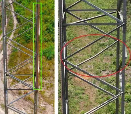
Figure 2: Corrosion (left) and plastic deformation (right). SOURCE: Kot Collection.
In addition, Kot performed dimensional checks on the structures to verify any discrepancies between the design specifications and the actual conditions on site. Subsequently, upon completion of the fieldwork, the collected data enabled the preparation of a visual inspection report, which included a mapping of the observed defects and nonconformities, as well as an assessment of their risks and the actions required for the towers’ restoration.
Finite element method (FEM) for structural analysis
The study progressed based on a structural analysis of the towers using the finite element method (FEM). To this end, it was necessary to review the design documentation as well as the field survey data. Accordingly, the model generated took into account the identified structural defects, as shown in Figure 3.
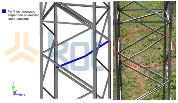
Figure 3: Representation of the plastic deformation identified in the field in the computer model. SOURCE: Kot Collection.
Structural analysis
The static analysis was the first of the checks performed, in accordance with applicable standards. During this process, the highest utilization factors (UFs) were found in structural members that were already compromised, either due to corrosion or warping. Consequently, the results were presented visually using a color-coded scale. As can be seen in Figure 4, bar elements with stresses exceeding the allowable limit (elements in red) were identified, highlighting the need for structural reinforcements.
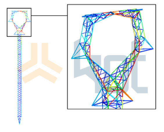
Figure 4: Utilization rates in tower bar elements. SOURCE: Kot Collection.
In addition, the analyses of the bar elements were performed using Kot's proprietary software, Procal . Visit LinkedIn or Kot’s to watch a video, in the words of Technical Director and head of Procal, Frederico Mol, about the main engineering tool used here at Kot.
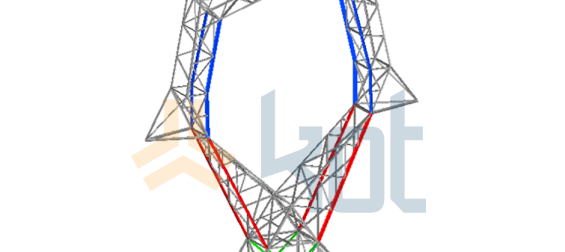
Similarly, the connections were analyzed in accordance with current regulatory criteria, using analytical methods and taking into account the various types of connections present in the structure. It was found that, under storm wind conditions (VT), the tower connections are susceptible to exceptionally high stresses, resulting in the possibility of bolt shear. On the other hand, under normal operating wind conditions (V0), the tower meets engineering standards. Figure 5 shows the elements with failed connections.
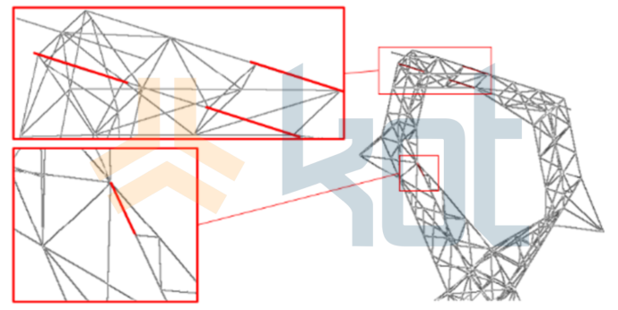
Figure 5: Elements with failed connections. SOURCE: Kot Collection.
In addition, the structure’s natural vibration modes were evaluated during the modal analysis to assess the possibility of any coupling or resonance between the towers and the wind. The results did not indicate any risk of coupling for longitudinal or transverse winds. Figure 6 shows one of the identified natural vibration modes.
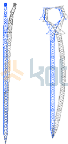
Figure 6: Natural vibration mode identified. SOURCE: Kot Collection.
Proposed solutions
In light of this, Kot proposed modifications to the upper portion of the tower to bring it into compliance with regulatory criteria and mitigate structural risks, as non-conformities were observed during the course of the work. After determining the proposed reinforcements, a structural verification was conducted to validate the recommended modifications. Finally, Figure 7 shows some of the suggested solutions.
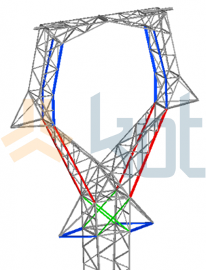
Figure 7: Proposed changes. SOURCE: Kot Collection.
Conclusion
In summary, the study identified several components in critical condition within the structures, exhibiting severe corrosion and plastic deformation, for which immediate replacement was recommended. Furthermore, the static analysis revealed that certain bar elements failed to meet requirements based on the U-values obtained, prompting the proposed structural reinforcements. Finally, Kot also proposed modifications to adapt the remaining structures to the storm wind scenario.
Kot has a team of qualified Structural Integrity professionals Structural Integrity to develop the best engineering solutions for your business. Contact our specialists for more information!
Follow our pages on LinkedIn, Facebook e Instagram to keep up with our content.
FAQ
1. Quais são as principais manifestações patológicas encontradas em torres metálicas de transmissão?
Em estruturas treliçadas expostas a intempéries e cargas dinâmicas, as não conformidades mais frequentes incluem:
-
Corrosão e oxidação: Perda de seção transversal útil dos perfis de aço galvanizado, reduzindo a capacidade de carga das barras;
-
Deformações plásticas (empenamento/flambagem): Alterações na geometria dos perfis provocadas por ventos excepcionais, impactos ou distribuição desequilibrada de tensões;
-
Folgas e avarias nas ligações parafusadas: Desgaste ou oxidação nos parafusos de fixação, podendo comprometer a rigidez do nó estrutural.
2. Como o Método dos Elementos Finitos (MEF) é aplicado no diagnóstico dessas estruturas?
O MEF permite criar um modelo tridimensional detalhado da torre treliçada para simular seu comportamento sob diferentes combinações de carga (peso próprio, tração dos cabos e ação do vento).
No estudo de integridade estrutural, as manifestações patológicas mapeadas em campo — como a perda de espessura por corrosão e as deformações plásticas — são incorporadas diretamente à geometria do modelo. Isso permite calcular com precisão o Índice de Utilização (IU) de cada barra e identificar quais elementos estão trabalhando acima do limite admissível ($IU > 1{,}0$).
3. Qual a diferença entre a resposta da estrutura sob ventos normais ($V_0$) e ventos de tormenta ($VT$)?
-
Ventos Normais de Operação ($V_0$): Representam as rajadas corriqueiras previstas durante o funcionamento habitual da linha de transmissão, nas quais as barras e ligações devem operar com folga em relação aos limites normativos.
-
Ventos de Tormenta ($VT$): Representam cenários críticos e excepcionais de alta velocidade. Na análise realizada, constatou-se que, enquanto as ligações atendiam às solicitações de $V_0$, a condição de $VT$ induzia tensões de cisalhamento excessivas nos parafusos das ligações, exigindo a adequação dos nós estruturais para evitar falhas catastróficas.
4. Para que serve a análise modal em torres de transmissão de energia?
A análise modal determina os modos e as frequências naturais de vibração da estrutura metálica. Seu objetivo principal é verificar se há risco de ressonância ou acoplamento aeroelástico entre as frequências da torre e a ação do vento (tanto em rajadas longitudinais quanto transversais). Caso haja coincidência de frequências, a estrutura pode sofrer vibrações descontroladas que aceleram a fadiga do material.
5. Quais soluções de engenharia são propostas após a identificação das falhas?
Com base nos resultados computacionais e de campo, as ações corretivas englobam:
-
Substituição imediata de perfis metálicos com deformações plásticas severas ou oxidação avançada;
-
Instalação de reforços estruturais (como contraventamentos ou adição de perfis paralelos) nas barras reprovadas na análise estática;
-
Redimensionamento e adequação das ligações parafusadas na geometria da parte superior da torre para garantir resistência total contra ventos de tormenta.