
The latest article published on Kot Blog addressed concepts such as: SDGs, accelerometry, modal analysis, and resonance.
Introduction
The need for mills in various mining processes is evident to professionals in the field, especially for grinding systems. This article will present one of Kot Engenharia success stories, Kot Engenharia the dynamic analysis of one such piece of equipment, the ball mill.
This type of mill consists of a cylindrical body containing several spheres, usually made of steel or cast iron, which are responsible for grinding the ore. This process occurs due to the movement of these spheres, which are lifted by the centrifugal force of the cylinder's rotation to a certain point, where they then fall onto the others still in the lower portion. Thus, when a material (in this case, the ore) is added to the assembly, the forces involved in the rolling and falling of the balls result in its fragmentation, as exemplified by the red balls in Gif 1.

Gif 1: Cataract regime in a ball mill – SOURCE: Kot Collection.
Due to the dynamic nature of the operation, anomalies in the support structures of this equipment are recurrent and usually manifest themselves through excessive vibration, cracks/fissures, and recurrent failures of anchor bolts or mechanical components. The insufficient rigidity and strength of the bearing support structures (e.g., beams, pillars, and concrete blocks) may be one of the factors responsible for the aforementioned non-conformities, aggravated by errors in the construction of the connecting elements (e.g., base plates, anchor bolts, and reinforcement frames) and by deviations in the assembly of the mechanical package.
In view of the problems mentioned above, Kot Engenharia essential to perform a dynamic structural analysis of this type of equipment, a process that allows the behavior of the assembly (structure, equipment, and foundation) to be studied for various operating scenarios (e.g., empty mill, full mill, speed changes, etc.). As a result, factors associated with excessive vibrations, fatigue, and other structural failures that lead to recurring downtime and repairs can be predicted and reduced.
Case description
A ball mill used in ore grinding had a history of anomalies in the concrete parts located below the drive pinion shaft support bearings. Excessive cracking and displacement of the concrete parts were initially attributed to the inadequate dynamic behavior of the assembly. In order to effectively diagnose and resolve the issues, Kot Engenharia the investigation campaign into the following stages:
- Structural analysis of the assembly;
- On-site measurements , data processing , and classification of vibration during operation;
- Visual inspection of structural anomalies.
The following are overviews of each of the stages and, finally, the conclusion and proposed solution based on the investigation.
Structural analysis
As already mentioned, dynamic structural analysis is a powerful engineering tool for this type of equipment. For this purpose, the finite element method (FEM) was used to perform this step. The following conditions were adopted for the analysis:
- Modeling of the reinforced concrete structure that supports the equipment;
- Consideration of soil-structure interaction;
- Consideration of the interaction between structure and equipment;
- Definition of structural excitation parameters, that is, determination of vibration levels resulting from the cataract inside the mill in operation.
Specific finite element software was used to develop the structural model of the mill base, in which solid (three-dimensional) elements were arranged to better represent the stress state in the material, as shown in Figure 1.
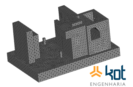
Figure 1: Finite element model of the mill – SOURCE: Kot Collection.
To evaluate the interaction between the soil and the structure, it is necessary to take into account the mechanical properties of the soil and the geometry of the equipment base. As a result of this analysis, it was concluded that, in addition to the deformation of the mill base caused by excitation, the movement due to the influence of this interaction (soil-structure) on the transient response of the concrete structure is also relevant.
The next step involves calculating the loads, when the structural mass, the mass of the mechanical equipment, and the dynamic loads resulting from the cascade formed inside the mill are defined. In this regard, it should be noted that the loads resulting from the cascade reaction vary over time due to their random nature. This results in dynamic excitation of the mill base, since the flow of falling material changes constantly, even with the constant rotation of the equipment.
With this in mind, the properties and loads involved in the material falling process were calculated using software developed by Kot Engenharia, which uses the ball mill operating concept. In addition, the results obtained were also evaluated based on experimental results already obtained by Kot in previous analyses.
To evaluate the results of this dynamic analysis, the velocity and acceleration envelopes of the structure under operating conditions were obtained, with an example shown below in Figure 2. The use of envelopes is a signal processing technique that enables the detection of faults at earlier stages, especially mechanical problems such as slack and loosening.
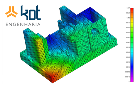
Figure 2: Envelope of accelerations in X in the structure [m/s²] – SOURCE: Kot Collection.
Based on the evaluation of this data, obtained through structural analysis, it was concluded that the mill foundations were dynamically adequate. This eliminated the dynamics of the foundation as a possible cause for the problems observed in the concrete structure, which supports the drive pinion shaft bearings. This conclusion is particularly valid when considering the design condition, i.e., that the structure was built and assembled in accordance with all design specifications. Therefore, it became necessary to investigate the structure inits 'as is'condition.
Vibration measurements and Structural Inspection
The next step was to calculate the vibration levels at the mill bases, which, as verified by Structural Inspection, were in critical condition due to inadequate cracking and displacement of the concrete under the base plate (soleplate) of the bearings. These bearings support the mill's drive shaft, and the inadequate quality of the concrete (due to construction deviations) was considered one of the possible causes of excessive vibrations in the drive system.
Vale that vibration is inherent to the process and its classification as "excessive" is based on regulatory requirements.
In this sense, the normatively permissible vibration levels vary according to the class of equipment, which is defined by power, type, and size, in addition to the flexibility of the base on which the equipment is installed. In addition, the vibration limits applied are based on dynamic loads on the bearings. Thus, the speed and displacement values are classified into zones, which define the operating condition of the asset:
- Zone A: Vibration characteristic of new machines;
- Zone B: Acceptable vibration levels for long-term operation;
- Zone C: Machines that exhibit vibration in this zone are considered unsatisfactory for long-term operation and must undergo scheduled maintenance;
- Zone D: High vibration values that cause damage to equipment. Immediate maintenance should be performed.
Next, in Figure 3 (left), we have an example of speed measurement in the bearings of the mill drive system. On the right side, a frequency spectrum is presented, which consists of the description of a given variable in the frequency domain, enabling the summary of vibration signals associated with the various frequencies that occur simultaneously. All vibration levels were measured at standardized points, in accordance with the reference standard.
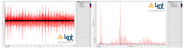
Figure 3: Speed [mm/s] (left) and frequency spectrum (right) in a bearing – SOURCE: Kot Collection.
With these results, the vibrations obtained were compared to the equipment's permissible levels, assessing the mill base's compliance with current standards. The vibration modes of the bases and columns were also analyzed, seeking to identify any possible relationship with the non-conformities observed.
Finally, the analysis of the collected data concluded that the vibration levels measured in part of the bearings were above the permissible values established by the standard, a condition that required corrective action. On these same bases, and only on them, the visual inspection revealed damage to the grout under the bearing base plates. This evidence led to the conclusion that certain factors were relevant, including the poor execution (construction) of the concrete under the base plates of the bearing connections.
Conclusion
It was possible to identify that some bearings had vibration levels below the permissible values according to the standard, while others were already in a condition that required immediate maintenance. The visual inspection revealed damage to the concrete under the bearing bases, with these anomalies being attributed to poor concrete construction, which failed under operating load conditions. As a result, the reduction in rigidity led to increased vibration levels in the assembly. A possible contribution from the anchor bolts was also noted.
This poor condition had a predominant influence on the higher frequencies of the spectrum, amplifying vibrations due to mechanical misalignments in the system.
Based on these conclusions, Kot developed a project to restore the pinion base. Structural restoration of the base connections and concrete parts supporting the bearings was necessary. Reinforcement bars were defined to ensure complete interaction between the materials that made up the base and to reduce cracking in the upper part of the base. As a result, the base now has satisfactory structural performance, with significantly reduced vibration levels after the restoration, and no longer presents the problems mentioned above during equipment operation.
If you need solutions in structural, modal, and dynamic analysis, KOT has qualified professionals and specific equipment to contribute to the Structural Integrity your asset. Since 1993, we have been specialists in developing engineering solutions through the use of computational methods. consult our team and learn about our services.
Follow our pages on LinkedIn, Facebook e Instagram to keep up with our content.


