
O monitoramento de componentes ferroviários utiliza sensores embarcados em rodeiros e engates para medir a interação roda-trilho e os esforços dinâmicos em tempo real. Apoiada na Fórmula de Nadal (L/V) e no método de contagem de dano por fadiga (Rainflow), a tecnologia identifica riscos de descarrilamento, desbalanceamentos de carga e desgaste prematuro, permitindo transicionar da manutenção preditiva para a prescritiva.
Veja como aplicar o monitoramento dinâmico no material rodante.
Introduction
Initially, in the 1950s, driven by the aeronautical industry's need to use more effective methods to diagnose and analyze causes and defects, the concept of Maintenance Engineering was developed with the aim of controlling and planning Preventive Maintenance.
Subsequently, starting in 1965, Reliability-Centered Maintenance (RCM) was implemented, which, although it accepted failure in the pursuit of zero failure, attempted to eliminate the consequences of failure. As a result, sophisticated measurement instruments and techniques capable of detecting symptoms at a very early stage began to be used increasingly.
The transition from reactive to preventive, predictive, and now prescriptive approaches represents a fundamental shift in both mindset and maintenance practices. As a result, strategies no longer focus exclusively on correcting faults, but rather on prevention, anticipation, and continuous monitoring of equipment performance. This results in less unplanned downtime, higher productivity, and reduced maintenance costs.
To apply these techniques on the railroad, monitoring the rolling stock, together with the loads on the couplings and accelerations of the wagon box, is essential to determine the condition of the infrastructure, the dynamics of the train and the iteration between the train and the permanent way.
Speed limitations on certain sections, track failures, derailments, and excessive loads on components, reducing their useful life, are common problems in railway operations. For this reason, these problems can be identified and corrected through indirect measurements, since monitoring the dynamics of the car associated with the loads on the couplings provides important elements for calibrating the computational model and detecting problems.
Succes story
Next, this case study will present how the instrumentation and data processing were carried out to identify defects.
Instrumentation
The components were instrumented at the Kot Engenharia workshop, with instrumentation being carried out on the two wheels of a roller and a coupling.
In addition, four extensometers were installed on the coupling in order to obtain the correct correlation between deformation and axial load. For greater measurement accuracy, the coupling was calibrated on a test bench, where tensile and compressive loads similar to those expected in the field were applied, as shown in Figure 1.
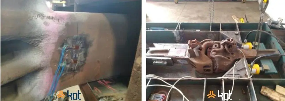
Figure 1: Extensometers and coupling calibration - SOURCE: Kot Collection.
To instrument the wheelset, a finite element model was first drawn up to determine the positions for installing the strain gauges. These positions were chosen to obtain the greatest deformations when applying lateral and vertical loads generated by the wheel-rail contact, as shown in Figure 2.
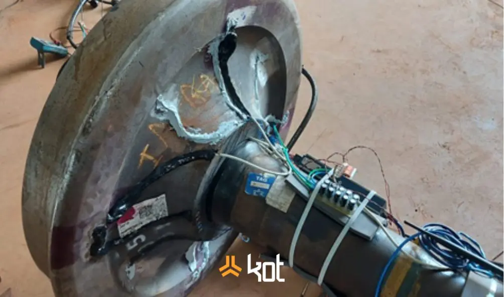
Figure 2: Instrumented wheeler - SOURCE: Kot Collection.
Subsequently, the deformation of the wheels was compared with the computational model after applying known lateral and vertical loads.
The wheelset monitoring system consisted of an on-board acquisition system on the axle, a battery pack in the wagon box, a main computer installed in the wagon, a power transmission system between the box and the wheelset, energy accumulators, filters, remote transmission systems and GPS.
Acquisition parameters
The deformations during the cycle were evaluated using a 2kHz acquisition rate and subsequent data filtering with a 25Hz lowpass to obtain the static loads on the coupling. A 4Hz highpass filter was used to obtain the dynamic loads on the coupling.
Next, the data from the wheel was acquired at 2000Hz and analyzed using the highest load amplitudes every 1 second to assemble the graphs and perform the analysis. Subsequently, the cross-deformation data was removed and the correlation between deformation and load was applied.
Measurement cycle
Nadal's formula is applied in railway projects by relating the vertical force exerted by the wheels to the lateral force of the wheel flange against the rail face. Consequently, this relationship is a widely used parameter to indicate the possibility of derailment. Figure 3 below illustrates the dynamics of derailment.
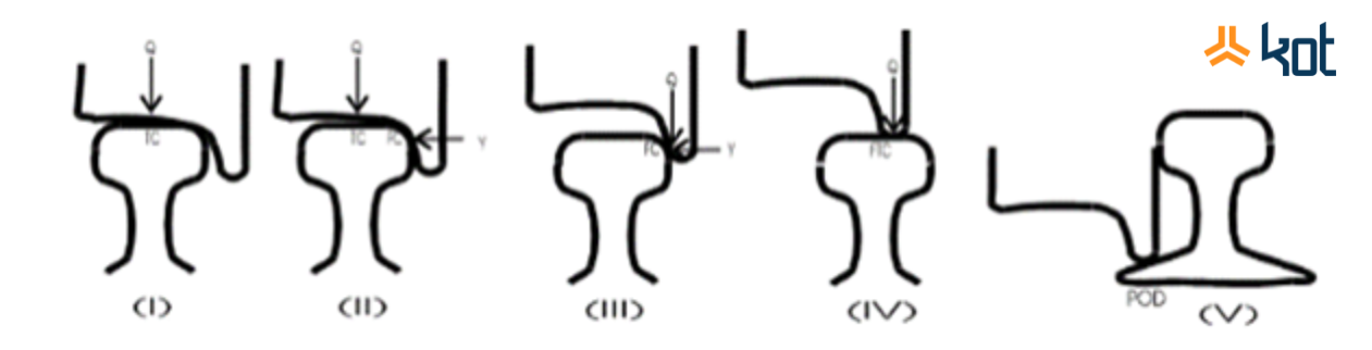
Figure 3: Derailment dynamics - SOURCE: MAHARAJPUR, Gwalior.
Nesse sentido, com o objetivo de facilitar a visualização dos pontos de interesse, os resultados são apresentados em formato de imagem, em que são indicadas as localidades onde foram identificados os alertas. Estes alertas foram configurados em dois níveis: alerta 01 (0.8 < L/V < 1.0 ou perda de carga entre 60% a 85%) e alerta 02 (L/V > 1.0 ou perda de carga acima de 85%).
The critical points identified in the measurement are shown visually in Figure 4.
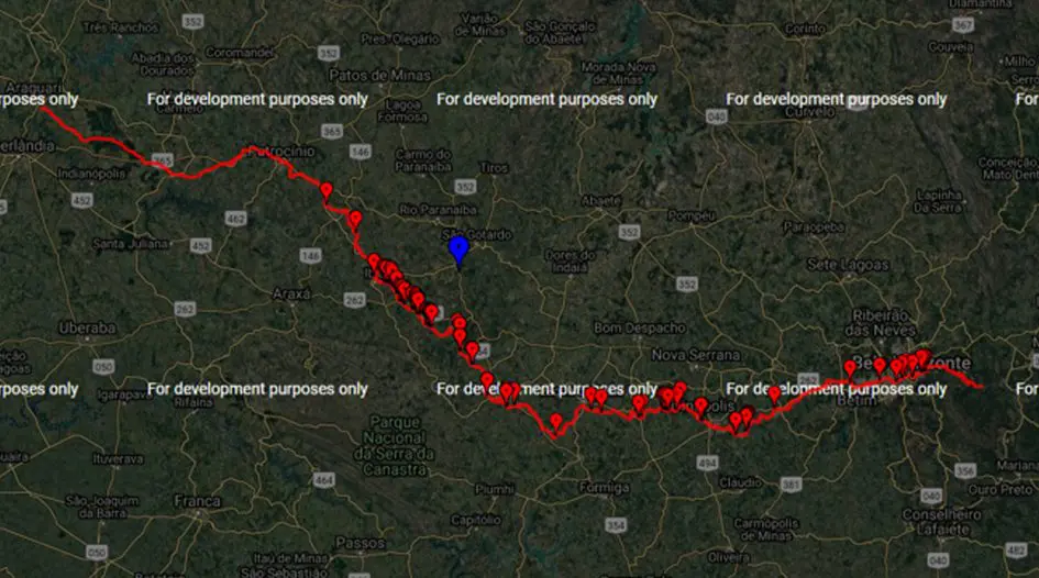
Figure 4: Example of a results map - SOURCE: Kot Collection.
Hitch loads
During train movement, especially during acceleration, deceleration, and cornering, dynamic forces are generated at the coupling and transferred to the permanent track. In fact, these forces can cause additional stress on the rails and fastenings, affecting the stability and service life of track components.
Thus, the joint measurement of these variables allows for a detailed assessment of the system, improving the maintenance strategy and impacting the inspection schedule for couplings. In cases of continuous measurement (instrumented railcar), the service life of components can be increasingly extended.
In addition to the dynamic loads to which the wagon is subjected, the position of the wagon in the train makes a significant contribution to increasing the load on the coupling for certain stretches, information that can be used by Maintenance Engineering to help optimize inspection intervals.
In the case study carried out, the loads measured on the coupling were presented in graph format, as can be seen in Figure 5 below.
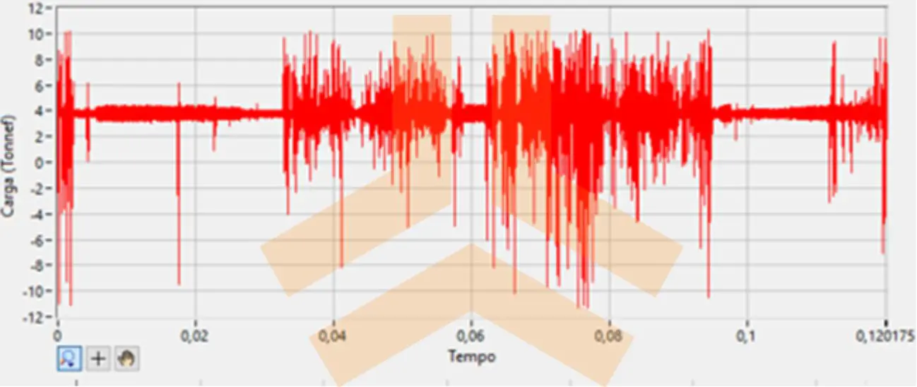
Figure 5: Loads acting on the coupling during an empty cycle - SOURCE: Kot Collection.
The values were treated statistically to support the fatigue calculation of the coupling and the components that depend on this iteration. The rainflow peak counting methodology was used and the component's fatigue life was defined using the Miner-Green damage count.
Conclusion
In conclusion, monitoring dynamic parameters of railcars allows the engineering team to diagnose problems and schedule maintenance more effectively. This made it possible to identify several operating variables, such as:
-
- Unbalanced load on the wagon. A difference of 20% of the nominal load on the wheels was identified between the left and right sides (possible loading problem);
-
- High L/V parameter values. Load imbalance alters the dynamics of curves, and this parameter works in conjunction with speed and track geometry. Better load balancing would allow for an increase in speed on certain sections;
-
- Hitch load warnings on bends;
-
- Identification of the loads on the coupling by their position in the composition;
-
- Low load on a stretch with a speed limit (monitoring can be carried out to change the speed on the stretch);
-
- Difference between driver operation and remote operation;
-
- Help in defining the composition assembly (locotrol or tricotrol).
Kot has a team of qualified professionals for the instrumentation and monitoring of railway components, excelling in the selection and application of the most appropriate methodologies for your business and your assets. Consult our team for more information!
Follow our pages on LinkedIn, Facebook e Instagram to keep up with our content.
FAQ
1. Como a Fórmula de Nadal é utilizada para prever e evitar o risco de descarrilamento de vagões?
A Fórmula de Nadal é um parâmetro fundamental da engenharia ferroviária que estabelece o limite de segurança para o escalamento do flange da roda sobre o trilho. Ela relaciona a força lateral (L), que empurra a roda para fora do trilho, com a força vertical (V), que mantém a composição no chão:
No monitoramento embarcado, os dados de deformação são processados em tempo real para gerar alertas preventivos em dois níveis:
-
Alerta 01 (0.8 < L/V < 1.0 ou perda de carga vertical de 60% a 85%): Sinaliza uma instabilidade dinâmica moderada, geralmente provocada por desalinhamento geométrico da via ou desbalanceamento de carga.
-
Alerta 02 (L/V > 1.0 ou perda de carga vertical acima de 85%): Indica alto risco iminente de o flange da roda subir o boleto do trilho e causar o descarrilamento.
2. Qual é a importância da modelagem por Elementos Finitos (MEF) antes da instalação dos extensômetros no rodeiro?
Instalar sensores de deformação (strain gauges) em um componente giratório e sujeito a solicitações complexas como o rodeiro exige precisão milimétrica. Antes de colar qualquer sensor em campo, a Kot constrói um modelo 3D em Elementos Finitos da roda para simular onde ocorrem as maiores deformações específicas sob cargas verticais e laterais. Essa simulação prévia garante que os extensômetros sejam colados exatamente nos pontos de maior sensibilidade mecânica, isolando o efeito da deformação cruzada e garantindo que as medições traduzam com precisão as forças reais entre a roda e o trilho.
3. Como os algoritmos de contagem Rainflow e Miner-Green calculam a vida útil em fadiga dos engates?
Durante a viagem, os engates sofrem variações aleatórias e contínuas de tração e compressão (esforços dinâmicos). Para transformar esse sinal caótico em estimativa de vida útil:
-
Filtro e Aquisição: O sinal coletado a 2 kHz é filtrado (highpass de 4 Hz) para isolar os picos de carga dinâmica.
-
Algoritmo Rainflow: Organiza a história temporal de carregamentos e agrupa os picos de tensão aleatórios em “ciclos de alternância de carga” discretos.
-
Regra de Dano Linear de Miner-Green: Soma o dano acumulado por cada ciclo em relação à curva S-N do material do engate. O resultado matemático indica com exatidão quantos ciclos ou viagens o componente ainda suporta antes do aparecimento de trincas por fadiga.
4. Como a detecção de um desbalanceamento de carga de 20% altera a velocidade permitida nas vias?
Se um vagão é carregado com mais peso de um lado do que do outro (desbalanceamento transversal), a força vertical (V) no lado mais leve reduz drasticamente. Ao entrar em uma curva, a força centrífuga gera uma força lateral (L) contínua. Como o divisor V diminuiu na roda mais leve, a razão L/V dispara, forçando a operação a aplicar restrições severas de velocidade naquele trecho para evitar o descarrilamento. Ao identificar esse desbalanceamento de 20% via instrumentação do rodeiro, a engenharia pode corrigir o processo de carregamento na tulha/silo, restaurando o equilíbrio de forças e permitindo um acréscimo seguro na velocidade operacional da composição.
5. De que forma o monitoramento dos engates auxilia na definição da distribuição das locomotivas (Locotrol vs. Tricotrol)?
A posição do vagão ao longo do trem afeta diretamente os esforços de tração e compressão (forças intra-composição) nos engates, especialmente em trechos com aclives, declives e curvas acentuadas. O monitoramento contínuo das cargas nos engates permite quantificar esses picos de tensão em diferentes pontos do trem. Com esses dados em mãos, a Engenharia de Operações consegue definir cientificamente a melhor estratégia de tração distribuída, como o Locotrol (locomotivas na frente e no meio) ou Tricotrol (locomotivas na frente, meio e cauda), reduzindo drasticamente os choques mecânicos e evitando o rompimento de engates.


