
The static weight of a railcar is only half the story. When in motion, dynamic oscillations generate mechanical load peaks that crush the ballast and misalign the track. Kot Engenharia on-site extensometers and finite element analysis to map the line’s actual Dynamic Amplification Factor, optimizing maintenance plans before structural failures occur.
1. Evolution of railway infrastructure and the role of ballast
Coal mining activities carried out in England in the 17th century gave rise to railroads, where the first transports used animal traction on rail-guided vehicles. Later, the invention of the steam engine allowed for significant evolution in railroad infrastructure, creating the first locomotive prototypes and enabling mechanical traction in freight cars.
The first railroads had their tracks supported on rigid blocks and, in some cases, directly on the ground. However, this construction model presented several problems in terms of track durability. In order to remedy these problems, the engineers of the time realized that more resilient supports were needed, capable of absorbing the impacts of operation.
In order to improve the resilience of the infrastructure elements of the permanent way, the need for a sleeper and ballast set was defined. For a material to be used as ballast, it must have characteristics such as:
-
- Resilience, adequate rigidity and the ability to distribute operating stresses;
-
- Ability to withstand and provide stability for lateral and longitudinal stresses and to maintain the geometry of the road;
-
- Capacity to drain rainwater.
The importance of these elements in the railway infrastructure is therefore evident, and care must be taken both with their correct dimensioning and with their maintenance during operation.
The passage of wagons and passenger cars generates longitudinal, lateral and vertical stresses due to wheel-rail contact, thus transferring loads to the sleepers and ballast of the permanent way. These loads cause the ballast to deteriorate, generating thinner elements and changing the track modulus. Knowing the loads helps define maintenance parameters.
2. Understanding the effects of yaw, pitch, and roll on rail freight
The definition of vertical loads acting on the permanent track is calculated statically, based on the weight of the railcar and its components plus its material load. However, there are dynamic movements of the railcar, such as yaw, pitch, and roll. In addition, each of these movements is characterized by rotations around the three axes of the wagon and occurs due to the transfer of mass from the damping system and the railway dynamics themselves, decreasing or increasing the loads on the wheels, as illustrated in Figure 1 and Figure 2.
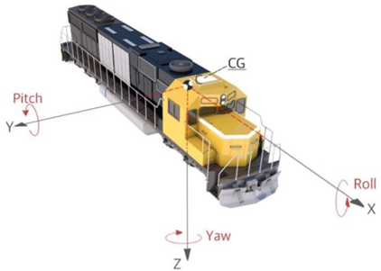
Figure 1: Yaw, pitch, and roll axes of rotation.
Source:FUNCTIONALITY ANALYSIS OF DERAILMENT CONTAINMENT PROVISIONS THROUGH FULL-SCALE TESTING—I: COLLISION LOAD AND CHANGE IN THE CENTER OF GRAVITY. Applied Sciences, vol. 12, no. 21, 2022. Available at: https://www.mdpi.com/2076-3417/12/21/11297. Accessed on: Nov. 26, 2024.
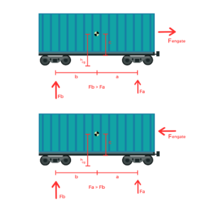
Figure 2: Reduction/increase in wheel load due to dynamic effects of the wagon.
Therefore, this load change, also called the dynamic amplification factor (Fd), is defined as the ratio between the dynamic load (Cd) and the static load (Ce), according to the following equation.

These load values may vary along the railroad due to the degradation of existing ballast, geotechnical factors in the region, and changes in system stiffness, such as railroad bridge entrances and exits, track defects, and rolling stock defects. Therefore, in order to obtain the actual values of the amplification coefficients, it is possible to conduct an experimental study to collect data in loco along the railroad. Check out one of the projects carried out by Kot below!
3. Succes story: Determination of the dynamic amplification factor of a railroad
In order to collect data on the dynamic amplification factors during the passage of railway trains over the track, strain gauges were installed on the rail, as shown in Figure 3.
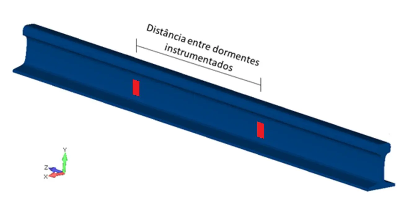
Figure 3: Instrumentation points.
The data acquisition allowed us to verify the deformation in the rail caused by vertical loads due to the passage of each wheel of the train, as shown in Figure 4. Thus, with this data, we can perform a finite element analysis and apply the loads to verify the sleepers and ballast in the analyzed region.
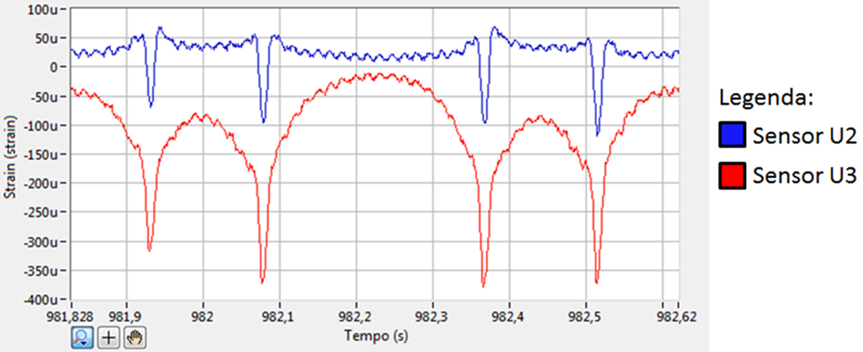
Figure 4: Typical measured deformation profile of the 4 wheels of a wagon.
To define the static loads, a loaded train passed the instrumented site at a speed of 5 km/h. From this data, the load values on the rails of 20 wheels were collected to obtain the average static stresses in order to remove possible effects of load unbalance, wheel defects, among others.
Next, after defining the static loads, the composition was measured at operating speeds on the section for collecting data on the dynamic factor of the road in question.
Finally, statistical calculations were used to define the upper control limits and the average of the data for the construction of the graph in Figure 5, presented below.
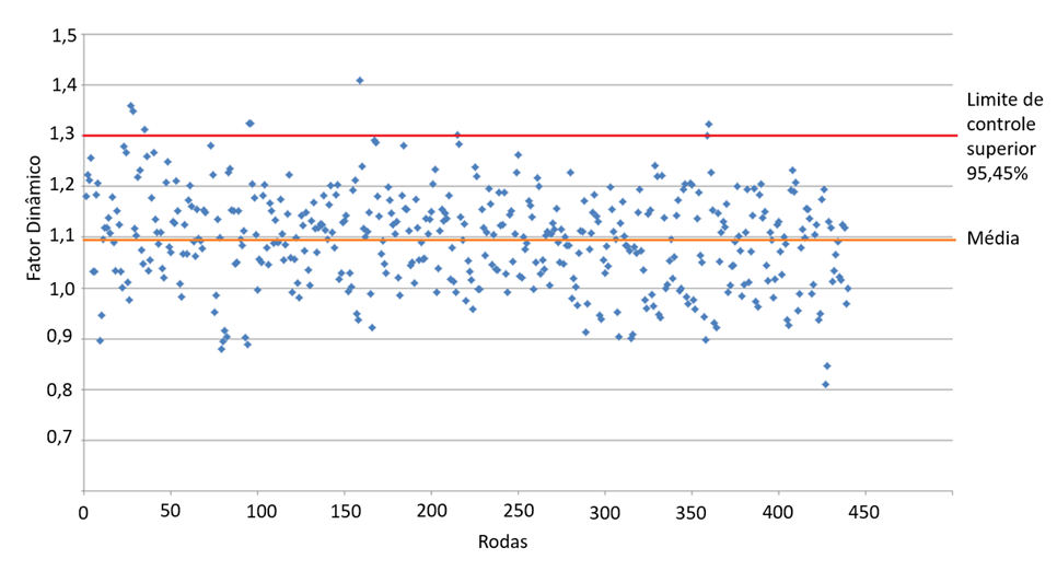
Figure 5: Dynamic factor values obtained during the study.
4. Impact of load measurement on railroad maintenance
Data collection made it possible to verify the actual loads acting on the permanent way components. In addition, the highest load amplification factor found in the section evaluated was 1.3, consistent with the literature (see Figure 6) for speeds of up to 60 km/h, adopted on Brazilian railways.
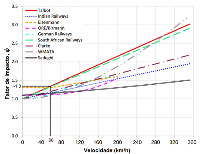
Figure 6: Dynamic amplification factors x speed according to international standards.
Vale that dynamic factors below 1 are expected and normal, and do not necessarily correspond to unrealistic values. The railcars exhibit various rigid body modes, such as pitch and roll motion, in addition to impact loads acting on the couplings, which cause excitations, resulting in variations in the loads acting on the bogies.
Infrastructure Analysis is with Kot Engenharia
If you, like our more than 150 clients, are looking for specialized solutions in structural analysis or failure prevention such as deformation, vibration, and corrosion, consult our team and count on Kot Engenharia.
Since 1993, we have been offering engineering consultancy services through technical studies using non-destructive testing, field instrumentation and computer simulations (FEM, DEM and CFD) for highly complex diagnoses of concrete and metal structures and industrial equipment.
Follow our pages on LinkedIn, Facebook and Instagram and keep following our content.
FAQ
1. How do yaw, pitch, and roll movements affect the forces on the train cars' wheels?
When the railcar moves, it does not travel in a perfectly straight line; the suspension system and track irregularities cause oscillations along three axes of rotation:
-
Yaw: Rotation around the vertical axis.
-
Pitch: Back-and-forth motion around the transverse axis.
-
Roll: Lateral tilting from side to side around the longitudinal axis.
These movements cause a constant and dynamic redistribution of the car’s mass. As a result, at any given moment, some wheels relieve pressure on the rail while others experience a load spike, creating an amplification effect.
2. Why does the Dynamic Amplification Factor vary along the same railroad line?
The Dynamic Factor is not constant because the stiffness of the track structure changes constantly. These variations occur due to geotechnical factors (different types of soil beneath the track), critical transition points (such as the entry and exit points of railway bridges, where the structure changes from flexible to very rigid), and areas with accumulated wear in the ballast itself or minor geometric defects in the rails and wheels.
3. Why was the speed reduced to just 5 km/h in the practical study to record the static load?
The measurement at 5 km/h serves to isolate and almost completely eliminate the dynamic effects of the car’s sway and impact. With the train nearly at a standstill, engineers are able to record the pure static load that each wheel exerts on the track. By averaging the forces from 20 wheels at this speed, they also eliminate statistical noise caused by minor load imbalances or surface imperfections on the wheels, creating a reliable baseline for comparison with actual operating speeds.
4. Is it normal to encounter dynamic factors less than 1 during field measurements?
Yes, this is perfectly normal and to be expected. Since the railcars function as rigid bodies hinged on the bogies (the structures that house the wheel axles), pitch and roll oscillations cause the railcar to “lift” slightly at some points while pressing down on others. When a wheel momentarily loses part of the load it would bear if the train were stationary, its dynamic factor (Dynamic Load / Static Load) becomes less than 1.


