
1. Application of GPR in concrete: advantages, limitations, and practical examples
Ground-penetrating radar (GPR) is a geophysical inspection method used to scan the surface in many applications, including concrete structures such as buildings, dams, and bridges. In this article, you will learn through practical examples how GPR is applied to concrete structures, as well as its main advantages and limitations.
2. Challenges in inspecting concrete structures and the role of non-destructive testing
In general, the main causes of processes that compromise the integrity of concrete structures are related to design, the choice of construction materials, the quality of construction, and the use of the structure throughout its service life.
In this regard, both destructive and non-destructive methods are used to assess the current condition of a structure. Although destructive methods can extract the necessary information from the structure, they are invasive and time-consuming procedures that can cause damage and contribute to the deterioration of the concrete. Furthermore, they often result in reduced availability of the asset for operation. Thus, Non-Destructive Testing (NDT) stands out as an alternative that allows for efficient inspection and evaluation without damaging the structure or requiring its shutdown.
Furthermore, the main NDT methods used for inspecting reinforced concrete structures are sonic/ultrasonic methods, infrared thermography, radiography, and electromagnetic methods. In this regard, the latter, which will be discussed in this article, utilizes radar technology that is rapidly gaining traction among NDT methods in the field of structural engineering, including applications in reinforced concrete structures.
In addition, the Ground Penetrating Radar (GPR) method allows for the detection of one or more layers of rebar embedded in concrete at depths of up to 80 centimeters. Furthermore, this test is quick to perform and, unlike sonic testing, provides visual results—features that make it a particularly useful tool for:
-
- Structures (or areas of them) where design documentation is poor or non-existent (typically old);
-
- Structures in which it is necessary to check the as-built condition of the reinforcement against the design;
-
- Assist in carrying out other tests in which the configuration of the reinforcement is relevant.
For example, Video 1, shown below, demonstrates its portability and speed of execution.
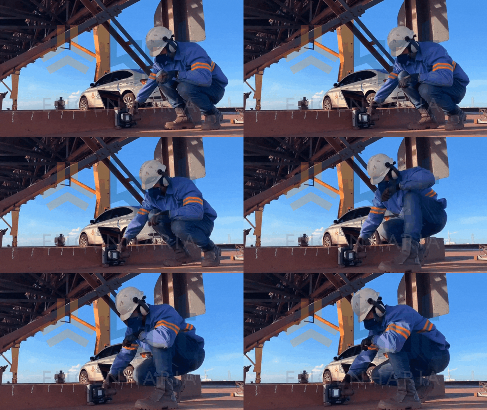
Video 1: Performing the GPR test. SOURCE: Kot Collection.
3. Ground Penetrating Radar in concrete
In fact, GPR for concrete is a relatively new non-destructive testing method in Civil Engineering allows for the identification, visualization, and mapping of objects within concrete. Furthermore, this technique has shown significant advancements over the past decade, particularly in locating reinforcing bars and estimating the cover depth of reinforced concrete.
In this regard, the operating principle of GPR is based on the transmission of an electromagnetic wave toward the surface of the material by a radar with a fixed center frequency using one or more antennas. The signal then returns to the device and exhibits characteristics determined by the properties of the material.
Figure 1 illustrates the test and the corresponding signal output. In general, the receiver first detects a forward wave that propagates through the air from the transmitter to the receiver on the surface of the material. Next, the electromagnetic wave, which passes through the concrete until it reaches the material with different dielectric properties (rebar), is reflected, and the receiver detects the wave by processing the signal.
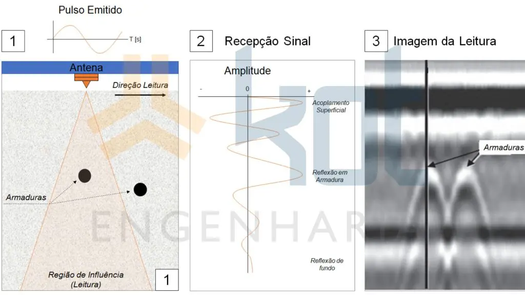
Figure 1: Example of a GPR test and corresponding signal output. SOURCE: Adapted from ACI 228.2R-13
Furthermore, with regard to standards—specifically those pertaining to concrete—ASTM D6087-08 provides detailed coverage of a series of GPR procedures for assessing the condition of bridge decks paved with asphalt concrete. ASTM D4748-15 specifies the determination of pavement layer thickness, and ASTM D6432-11 specifies subsurface investigation.
3.1. Advantages
-
- Reliability of results;
-
- Fast data collection compared to destructive tests tests;
-
- Fast results with high-resolution images;
-
- Suitable for external surveys;
-
- Useful information on the main structural elements.
3.2. Limitations
On the other hand, the limitations include:
-
- Complexity in interpreting results;
-
- Limited depth range on the surface.
Figure 2 shows different ways of visualizing the results carried out by Kot Engenharia in the same area of a reinforced concrete structure.
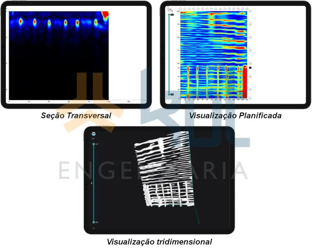
Figure 2: GPR results on a reinforced concrete structure. SOURCE: Kot Collection.
3.3. Example of application
For example, GPR was used to assess the condition of a reinforced concrete foundation belonging to a conveyor belt. The objective was to verify and confirm the condition of the structure in relation to the original design using non-destructive testing.
The pile load testing allowed us to locate the reinforcement and also estimate the diameter of the bars and the concrete cover. However, obtaining a sufficient number of results (readings) was difficult due to equipment limitations and the adverse geometric conditions encountered in the tested structure. Consequently, GPR was used as a complementary test in the process of verifying the reinforcement.
The equipment used for the test was a Proceq GP8000 with stepped frequency continuous wave technology, a modulated frequency range of 200 - 4000 MHz and a penetration depth of up to 80 cm.
Finally, the results obtained by GPR (Figure 3) indicated compliance with the design by identifying the first- and second-layer reinforcement on the faces where the test was conducted.
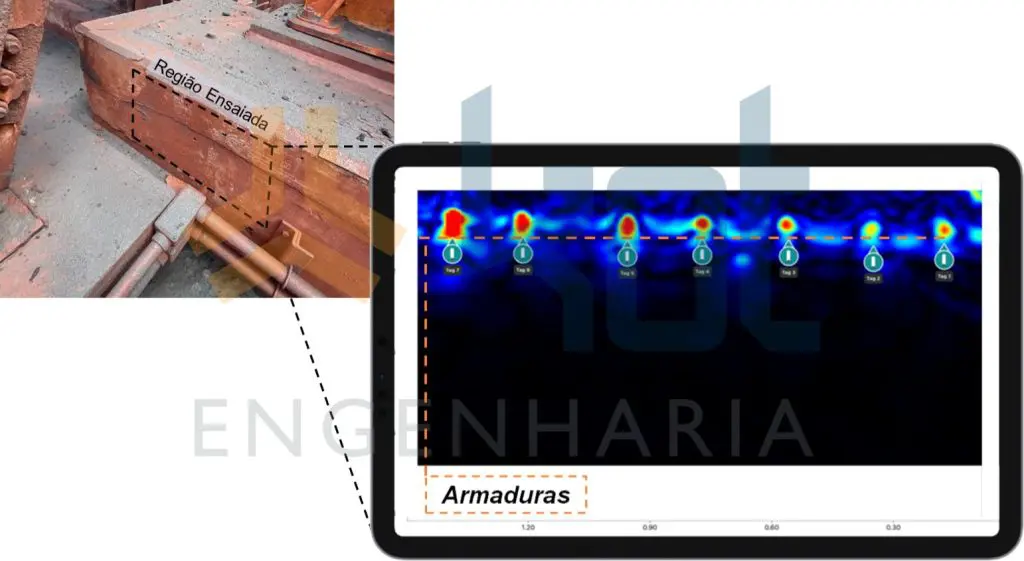
Figure 3: GPR test on reinforced concrete structure. SOURCE: Kot Collection.
4. GPR as a strategic solution for the diagnosis and management of concrete structures
In summary, the GPR non-destructive testing method enables efficient inspection and assessment. Furthermore, it has other applications in Civil Engineering and has proven effective in locating reinforcing bars and estimating their cover depth.
Thus, its ability to provide rapid imaging results on key structural elements in a short period of time demonstrates the versatility of this NDT method.
Finally, it should be noted that, as a relatively new method that has seen significant advancements, GPR—combined with the ability to interpret its results—is a highly valuable tool for assessing the condition of reinforced concrete structures. Therefore, this study contributes to the sustainable development of Structural Integrity management systems, as well as maintenance and quality control in construction.
GPR is with Kot Engenharia
If you, like our more than 150 clients, are looking for specialized solutions in structural analysis or failure prevention such as deformation, vibration, and corrosion, consult our team and count on Kot Engenharia.
Since 1993, we have been offering engineering consultancy services through technical studies using non-destructive testing, field instrumentation and computer simulations (FEM, DEM and CFD) for highly complex diagnoses of concrete and metal structures and industrial equipment.
Siga, também, nossas páginas no LinkedIn, Facebook e Instagram.
FAQ
1. O que é a tecnologia de amplificação de movimento (câmera IRIS M™) e por que ela supera a acelerometria tradicional nesse caso?
A tecnologia de amplificação de movimento utiliza processamento avançado de vídeo para detectar deslocamentos imperceptíveis ou sutis na estrutura e amplificá-los visualmente em tempo real.
| Parâmetro | Acelerometria Tradicional | Análise por Imagem (Câmera IRIS M™) |
| Tempo de Instalação | Elevado (exige fixação de dezenas de sensores e cabos). | Instantâneo (medição óptica à distância, sem contato). |
| Mapeamento de Campo | Pontual (restrito aos locais onde há acelerômetros). | Global (cada pixel do sensor da câmera atua como um ponto de medição). |
| Visualização do Modo | Exige interpolação complexa e demorada de sinais. | Exibe visualmente o modo de vibração real do equipamento em minutos. |
2. Quais foram os principais sintomas e anomalias detectados no tanque de polpa?
Em condições específicas de rotação do agitador e nível de polpa, o tanque apresentava vibrações severas e visíveis a olho nu. Essas oscilações geraram trincas precoces na base de concreto e, como revelado pela amplificação de imagem, provocaram o levantamento dinâmico (lifting) do fundo metálico em relação à fundação civil durante os picos de cada ciclo.
3. Como os dados da câmera foram integrados à Análise por Elementos Finitos (MEF) e à avaliação de fadiga?
Os deslocamentos e frequências capturados pela câmera IRIS M™ serviram para calibrar com precisão o modelo computacional do tanque no software MEF. A partir dessa calibração, foi realizada uma Análise de Vibração Forçada:
-
Mapeamento de Tensões: Identificou-se a distribuição exata de tensões e deformações cíclicas ao longo de todo o costado metálico;
-
Análise de Fadiga de Alto Ciclo: Os cálculos demonstraram que manter o equipamento operando na condição crítica por cerca de 200 horas resultaria no surgimento de trincas nas soldas do costado, com risco iminente de colapso.
4. Qual foi a solução recomendada e quais foram os impactos operacionais e financeiros?
A solução consistiu na adequação do procedimento operacional através da redução da rotação do agitador nos níveis críticos de polpa, afastando a fonte de excitação da frequência natural da estrutura. Essa medida reduziu a amplitude de vibração no costado em cerca de 40 vezes e eliminou o risco de trincas por fadiga, mantendo a capacidade de homogeneização do processo intacta e evitando investimentos em reforços físicos ou prejuízos com paradas de fábrica.