
Kot Engenharia structural and mechanical analysis of a 4,200 t/h forklift, identifying areas of concern and opportunities to increase equipment reliability and safety. So, if your operation depends on large assets and requires informed technical decisions, keep reading.
1. Introduction to the structural and mechanical analysis of ore stackers
Ore stackers are yard machines commonly used in stockyards to form piles of material. To this end, it has a metal structure that includes translation, turning and tilting systems. It is therefore necessary to evaluate the equipment in terms of both structural criteria and mechanical systems.
Kot Engenharia responsible for verifying the design of a forklift truck with the aim of bringing it into line with the regulatory standards of a client company. This is because such compliance is necessary to assess the safety of assets and thus avoid catastrophic consequences for people and the environment.
The equipment in question transports iron ore, with a capacity of 4,200 t/h. In addition to analyzing the regulatory requirements, the study also included the structural, global stability, modal and mechanical analysis of the machine, which will be presented in this case study.
2. Three-dimensional modeling of the forklift
The first step in the structural analysis process using the finite element method is to model the structure. Specifically, in the case of the forklift, the structural model was developed using bar and shell elements for regions composed of profiles and structural plates, respectively. The subsystems are shown in Figure 1.
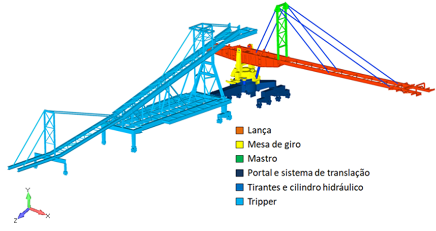
Figure 1: Complete finite element model of the structure.
The loads applied to the model include self-weight, material load, belt traction for different operating regimes, material fouling load on the structure, overloads, chute clogging, among others. These loads were combined for different considerations, as required by the standard, in order to carry out the structural and mechanical analysis.
3. Structural and mechanical analyses performed
3.1. Static analysis
During the static analysis of the lower part and the tripper of the forklift, utilization rates above the permissible level for the structure's overload operating condition were verified. As a result, this condition failed both the tripper bar elements (Figure 2) and the shell-modeled elements of the turntable (Figure 3).
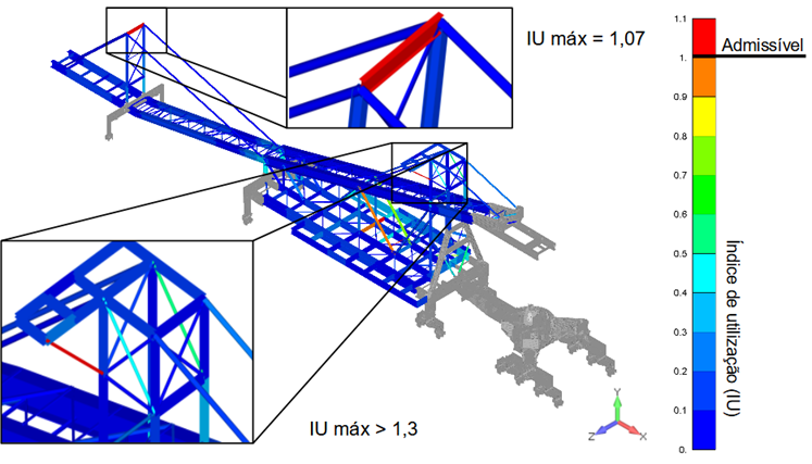
Figure 2: Envelope of utilization rates in tripper busbar elements for overload operation.
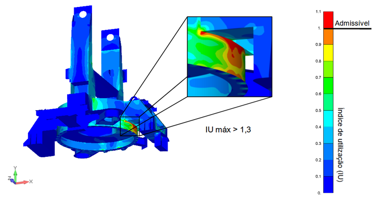
Figure 3: Envelope of utilization rates in turntable shell elements.
3.2. Fatigue analysis
Fatigue analysis was performed considering the number of cyclic repetitions specified by the standard. Consequently, utilization rates above the permissible level were identified for the rear of the boom and the turntable, as can be seen in Figure 4.
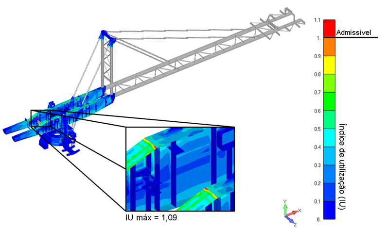
Figure 4: Fatigue utilization rates of shell elements.
3.3. Local buckling analysis
Local buckling analysis is carried out for shell-modeled elements, in which the acting von Mises stresses, after calculating the eigenvalues, are compared to the permissible stresses. This is an important check for regions typically subjected to compressive loads, which can generate the effect of local elastic failure of the components. The structure was approved, as shown in Figure 5.
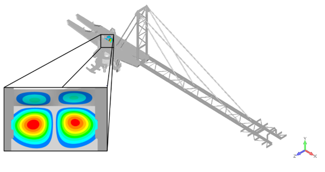
Figure 5: Buckling mode - approved structure.
3.4. Link analysis
Welded rigid connections failed at the top of the tripper tail mast for the overload combination. The same occurs for rigid end plate connections when evaluated in combinations with chute fouling loads and wind loads.
3.5. Overall stability analysis
This type of analysis considers a stability polygon, in which each edge is considered an axis of possible overturning, as shown in Figure 6. In addition, this analysis rejected the structure for combinations with boom overload.
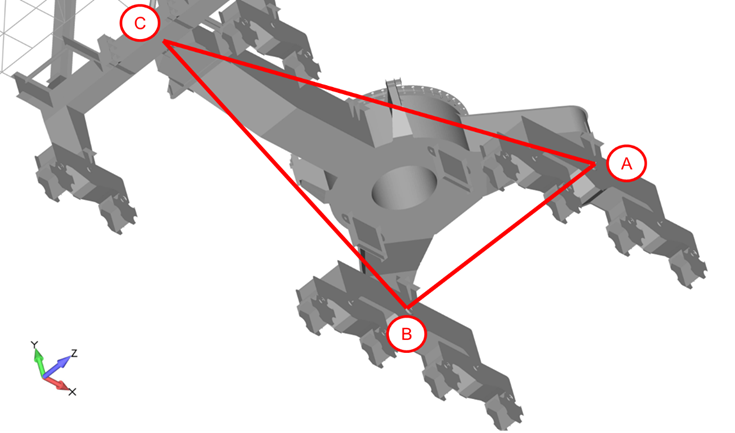
Figure 6: Stability polygon considered in the analysis of the complete forklift truck.
3.6. Modal analysis
Modal analysis indicates the possibility of the structure resonating with exciting sources. These sources can be, for example, wind, drums, boom conveyor rollers and belt oscillation. Some warning situations were found, as shown in the deformed view in Figure 7, which occurs when belt oscillation is an exciter source.
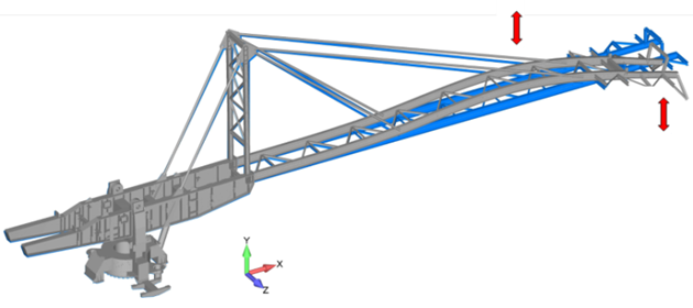
Figure 7: Deformation from modal analysis.
3.7. Mechanical analysis
The mechanical analysis included the belt conveyor located on the boom and the tipping, turning and translation systems. Some of the non-conformities found were:
-
- One of the drums does not have a standard minimum diameter;
-
- The turning system was non-compliant in terms of the pressure installed to turn the machine, the brake and the bearing;
-
- In the drive system, slipping of some of the wheels is to be expected.
4. Conclusions and recommendations
This case study shows the need to evaluate structures in overload situations, whether they are roofs, walkways, operating or maintenance platforms. Normative criteria must be followed and providing for this type of loading is essential to mitigate the risk of structural collapse.
With this in mind, Kot Engenharia actions to be followed by the client to adapt the equipment so that it operates according to the required standards. These actions include both structural reinforcements and machine monitoring.
5. Structural analysis is done by Kot Engenharia
Kot Engenharia extensive know-how in the structural and mechanical analysis of forklifts and yard machines in general.
If you, like our more than 150 clients, are looking for specialized solutions in structural analysis or failure prevention such as deformation, vibration, and corrosion, consult our team and count on Kot.
Since 1993, we have been offering engineering consulting services through technical studies using non-destructive testing, field instrumentation, and computational simulations (FEM, DEM, and CFD) for highly complex diagnostics in concrete and metal structures and industrial equipment.
Follow our pages on LinkedIn, Facebook and Instagram and keep following our content.
FAQ
1. Por que o modelo computacional da empilhadeira dividiu a estrutura entre elementos de barra e de casca?
Essa divisão é fundamental para garantir a precisão matemática da simulação sem inviabilizar o custo computacional do modelo. Os elementos de barra (unidimensionais) foram aplicados nas regiões compostas por perfis estruturais e treliças, como o tripper e o mastro, onde o esforço principal é de tração, compressão ou flexão linear. Já os elementos de casca (bidimensionais) foram adotados em regiões formadas por chapas finas e geometrias complexas, como a mesa de giro e o costado da lança. Essa abordagem híbrida revelou com exatidão que a sobrecarga de operação causava o escoamento do material tanto nas barras do tripper quanto nas chapas da mesa de giro.
2. Como funciona o polígono de estabilidade global e por que a empilhadeira falhou nesse teste?
O polígono de estabilidade é uma representação geométrica formada a partir dos pontos de apoio da máquina sobre os trilhos (as posições dos truques de translação). Cada linha (aresta) que conecta esses apoios funciona como um eixo virtual de um possível tombamento. Na simulação, ao combinar o peso próprio da máquina com o efeito de incrustação de minério e a sobrecarga na ponta da lança, o Centro de Gravidade (CG) do conjunto deslocou-se para fora dos limites seguros desse polígono. Como o momento de tombamento superou o momento restaurador do contrapeito, a estrutura foi tecnicamente reprovada por risco real de queda.
3. Qual é o perigo real da advertência gerada pela análise modal sobre a oscilação da correia?
A análise modal mapeia as frequências naturais de vibração da máquina, ou seja, o “ritmo” em que a estrutura balança sozinha se for estimulada. O perigo surge quando uma fonte excitadora externa — neste caso, a vibração cíclica provocada pela oscilação da correia transportadora da lança — opera em uma frequência muito próxima a uma dessas frequências naturais da empilhadeira. Isso gera o fenômeno da ressonância, que amplifica drasticamente a amplitude das vibrações na estrutura. O resultado prático disso é o surgimento de picos de tensão alternada que aceleram a fadiga do metal e rompem ligações soldadas prematuramente.
4. Quais foram as principais não conformidades mecânicas encontradas nos sistemas de giro e translação?
A análise mecânica detalhada detectou problemas de subdimensionamento que impactam diretamente a operação do ativo:
-
Sistema de Giro: A pressão hidráulica instalada não era suficiente para vencer o torque de atrito necessário para girar a máquina sob condições normativas severas, além de o conjunto de freio e o rolamento de giro operarem acima da capacidade segura.
-
Sistema de Translação: A distribuição desigual de cargas nos truques indicou a tendência de patinagem (escorregamento) de algumas rodas sobre os trilhos, o que gera desgaste acelerado nos flanges e desalinhamento crônico da empilhadeira durante a movimentação no pátio.


