
This article will present a success story by Kot regarding the structural analysis of a forklift. Before beginning the case study, some basic supporting concepts are outlined below.
Basic concepts of structural analysis
-
- Yard machines: these are widely used, especially in mining and port activities for handling bulk cargo;
-
- Forklift trucks: yard machines used to form stacks of bulk materials;
-
- Tripper: mobile belt conveyor, connected to the forklift, responsible for lifting the material supplied by the conveyor from the yard to the stacking machine;
-
- Bar element: a type of one-dimensional element used in the finite element method (FEM). It has the geometric property of a cross-section and is often used to represent metal profiles;
-
- Shell element: a type of two-dimensional element also used in FEM. Its geometric property is its thickness and it is commonly used to represent structures made up of metal sheets;
-
- Plasticization: behavior that materials exhibit when subjected to stresses that generate internal tensions beyond their elastic limit. Plasticization is exemplified by permanent deformations in the material;
-
- Utilization index: ratio between the acting forces (or stresses) and those resisting the structure. Calculated values less than or equal to 1.0 correspond to the normative approval condition.
The forklift analyzed by Kot has a design capacity of 20,000 t/h (tons per hour) and is responsible for forming the ore pile in a storage yard.
3D modeling
First, the equipment under analysis consists of the forklift and the tripper, which were modeled using finite elements to enable the study to begin. For the truss structures, beam elements were used because they are profiled. Meanwhile, the other components of the machine, which have greater geometric complexity—such as variable-section profiles, metal plates, local reinforcements, and stiffeners—were represented using shell elements.
As shown in Figure 1.1, the forklift model includes all of the equipment’s subassemblies:
-
- Tricks;
-
- Table and portal;
-
- Turning system;
-
- Mast;
-
- Launch;
-
- Counterbalance;
-
- Intermediate mast;
-
- Rods.
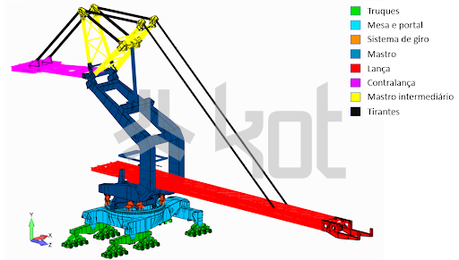
Figure 1.1: Forklift model. [1]
The tripper model, illustrated in Figure 1.2, shows all the metal profiles used.
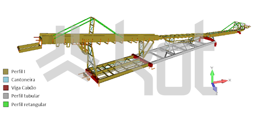
Figure 1.2: Tripper model. [1]
Subsequently, the loads applied to the structures were combined in accordance with the standard, so that different operating conditions could be evaluated, covering all standard cases. Additional combinations, defined based on Kot’s experience, were also used.
Among the charges imposed, the following stand out:
-
- Own weight of the structure and installed equipment;
-
- Material load and fouling;
-
- Belt tension in the permanent and transient regimes;
-
- Overloads;
-
- Shock against the pile of material.
Structural analysis
First, a static analysis was performed. In this analysis, the profiled structures showed no nonconformities. On the other hand, in the shell-modeled structures, utilization factors above the permissible limit were found in the tip region under normal operating conditions, as shown in Figure 1.3.
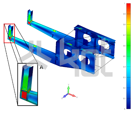
Figure 1.3: Utilization rates in elements of the boom discharge region. [1]
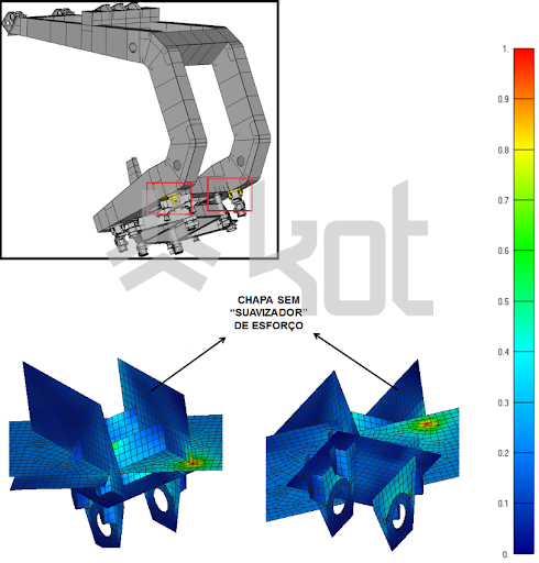
In addition, at the point where the mast connects to the swivel brackets, a non-conformity was found in the mast beam stiffener, which lacks a gusset plate to relieve the stresses acting in that area. As a result, the existing component concentrates all the applied stress, creating a stress peak. This non-conformity is shown in Figure 1.4.
However, a direct comparison of applied and design stresses alone is not always sufficient to determine a structure’s strength within a structural analysis. Instability phenomena in this type of equipment are very common—whether due to operational movements, operational overloads, wind loads, or other regulatory factors considered—and tend to arise at stress levels typically lower than the elastic limits of the materials used. Thus, to verify these limit states, a local buckling analysis was performed, focusing on the regions where the highest compressive loads were found, as these are more susceptible to buckling. In the lower part of the model, for example, these regions are located on the top flange of the equalizing beams, as shown in Figure 1.6.
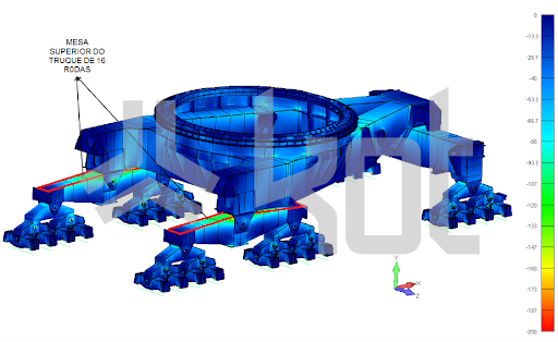
Figure 1.6: Maximum compressive stresses in the bottom model. [1]
Once the verification of the structures’ static strength is complete, the assessment of the equipment’s service life begins through fatigue analysis. Within the structural analysis, this evaluation consists of determining the operational strength—that is, the structures’ ability to withstand nominal loads throughout their service life—and is usually performed in accordance with the equipment’s cyclic operating regimes.
For the forklift, a 35-year operating life was assumed in the fatigue analysis. In the mast, utilization rates exceeding the permissible limit were found in regions that, in the static analysis, were prone to plastic deformation and exhibited stress concentrators. Consequently, the points indicated in Figure 1.5 have the potential for crack initiation and propagation.
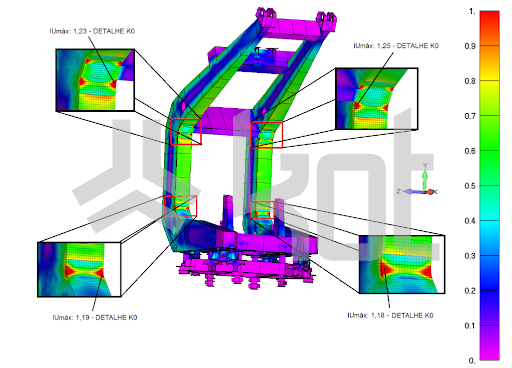
Figure 1.5: Maximum fatigue utilization rates on the mast. [1]
In addition, the different types of connections between the structures were also analyzed, including rigid and flexible, welded, and bolted connections. In this evaluation, the beam connections shown in Figure 1.7 failed the analysis for the load combination involving an impact load against the ore pile. Although the standard on which the verification was based does not provide for this type of loading for forklifts, Kot Engenharia included Kot Engenharia in the structural analysis because it is a possible scenario and, if it were to occur, would be critical for the structure.
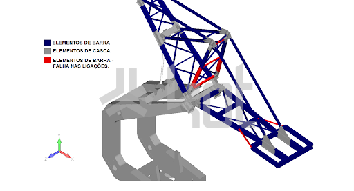
Figure 1.7: Profiles with failed connections in the pile-driving combination. [1]
In addition, a flexibility check—which involves calculating and evaluating structural displacements—was also performed. The conclusion of this stage resulted in warnings regarding the platforms and main longitudinal members of the boom. Although this does not affect the equipment’s operation, it is important to monitor these areas, as displacements exceeding the permissible limits may cause damage to non-structural elements and discomfort to users.
Similarly, another important check for yard machines is overall stability. Since the forklift’s lower carriage has three pivot points, the equipment’s stability polygon will be a triangle, as shown in Figure 1.8. Thus, each side of the triangle represents an axis of potential tipping. It was verified that all minimum stability coefficients are within acceptable limits, and the forklift was deemed to have passed this requirement.
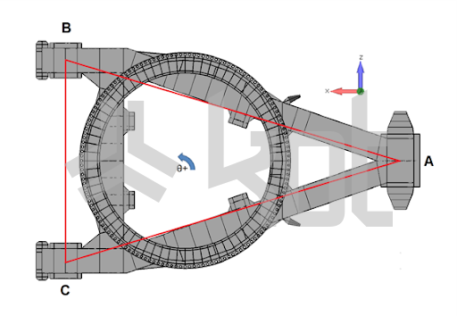
Figure 1.8: Stability triangle. [1]
Finally, the machine's jacking points were checked for their structural strength, in accordance with international standards. The jacking can be carried out at different points to maintain each of the bogies, rocker arms or equalizer beams. The reinforcement ribs, in the area that serves as the jacking point for maintaining the slewing bogies, showed utilization rates above the admissible level, as can be seen in Figure 1.9.
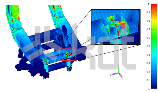
Figure 1.9: Static analysis in the jacking condition. [1]
Conclusion
In summary, the structural analysis of the forklift revealed non-conformities in some cases. Consequently, Kot recommended modifications, reinforcements, and monitoring. It is important to note that different regions exhibited stress concentrations, which led to high stress levels in both the static and fatigue analyses. This occurs because the design often does not take into account discontinuities that may contribute to this effect, such as [2]:
-
- Sudden changes in the thickness or geometry of the cross section;
-
- Notches, holes and keyways;
-
- Error in the basic design of the equipment;
-
- Faults generated during the manufacturing process.
Therefore, with this in mind, it is essential that projects be evaluated by structural engineers. If your company needs to have its machinery and equipment inspected, please contact our team and learn more about our services!
Follow our pages on LinkedIn, Facebook e Instagram to keep up with our content.
References:
[1] Kot Collection.
[BUDYNAS, R. G.; NISBETT, J. K. Shigley's machine elements: mechanical engineering design. AMGH Editora, 2011.


