
Operating metal chimneys without refractory lining at temperatures above 450°C exposes the steel to creep—a continuous and permanent plastic deformation that distorts the side walls and causes the structure to buckle. Kot Engenharia the root cause of this problem in a critical asset by combining infrared thermography and nonlinear finite element analysis (FEA). The solution made it possible to redesign the free-expansion supports, increasing the service life of the welds under thermal fatigue by 350%.
1. Introduction to thermal expansion and creep in metals
Every structure is subjected to different types of load, which it is up to the designer to take into account correctly when designing the equipment. Gravitational loads, wind loads and overloads are some typical examples of stresses on structures and equipment. In addition to these loads, thermal loads are extremely important for Structural Integrity, since they impose internal stresses on the elements to counteract the thermal expansion they undergo.
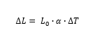
In general, structures exposed to the weather and built in regions with normal climatic conditions (conveyors, buildings, yard machines, etc.) are subject to temperature variations throughout their lifetime in the order of 20°C. In locations with extreme climatic conditions, higher values may be reached, such as in the Gobi Desert, where temperatures reach 45°C in summer and -40°C in winter. Thus, to calculate the change in linear length of a body due to the action of temperature, the following formula is used:
Consequently, thermal expansion converts into internal stress in an element if the deformation is restricted by the external environment. See the example in Figure 1, which shows the same beam with two different boundary conditions. The beam on the left, which is simply supported, expands uniformly without changing shape when heated from 20°C to 100°C. Therefore, in this condition, no forces contrary to the movement of the structure are generated from thermal expansion, and the resulting stress from the thermal load is negligible. In the beam on the right, which is fixed at both ends, thermal expansion is restricted by the support, resulting in forces contrary to expansion, thus altering the shape and generating stresses in the structure. In summary, this simple example illustrates the general consideration of temperature effects on structural design. Figure 2 shows the deformation of a railroad track when subjected to temperature variation.

Figure 1: Reactions and deformations of a simply supported beam (left) and a doubly braced beam (right) when heated.

Figure 2: Axially constrained rail deformed due to thermal expansion.
2. How temperature affects internal stresses
Thermal-structural analysis is performed to evaluate the influence of thermal load on deformations and, consequently, on stresses. In the context of analysis using the finite element method, there are two ways to consider this interaction: weak and strong thermal-structural coupling. In this sense, weak coupling consists of performing a thermal analysis to determine the temperature field and using this data as input in the structural model, without the change in one parameter influencing the other. In turn, strong coupling solves the equations concurrently, considering the interaction between the solutions (see an example of coupling between phenomena in the FSI article).
3. Thermo-structural analysis methods (FEM)
The most common way of carrying out thermo-structural analysis is by means of weak coupling, as it has lower computational costs and minimal differences for most engineering problems.
In addition to the stresses generated by thermal expansion reactions, there are other important effects to consider during design. Based on this, this article will discuss the concepts of creep, ways to consider this effect on structural strength, and a case study that illustrates the importance of considering creep in the structural safety of a chimney.
4. Fluency: stages and impacts on Structural Integrity
Metal creep is a phenomenon that occurs when a material is subjected to constant stress and continues to deform over time. For example, imagine a double-supported beam that supports the weight of an engine. If the beam is at room temperature (20°C to 40°C), it will deform when the engine is placed on it and then remain static with constant deformation. However, if that same beam is subjected to a temperature of 500°C, depending on the level of stress, it will continue to deform and may collapse.
In addition, creep occurs more quickly at high temperatures, such as in aircraft engines or turbines, where metal parts are simultaneously subjected to intense heat and stress. Over time, this deformation can affect the integrity of the material, a factor that must be taken into account during design.
Thus, the phenomenon is characterized by three stages: the first is transient, in which the structure deforms due to external loads and partly due to the creep effect; the second is a steady and constant deformation; finally, the third stage is unstable and may culminate in material failure. Figure 3 shows the typical setup for creep tests and the three phases explained above.
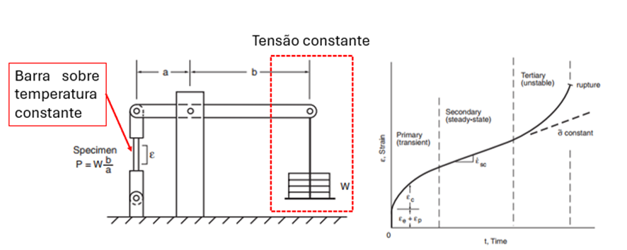
Figure 3: Diagram of a typical creep test, illustrating the three stages of deformation observed in the specimen. SOURCE: Adapted from Dowling - 2013.
"Creep deformation in metallic materials becomes significant at temperatures above the range of 30 to 60% of the material's melting temperature"– Dowling – 2013. Creep analyses can be considered in different ways. The most simplified approach used for structural designs subjected to fire is the reduction of the modulus of elasticity and yield strength as a function of the acting temperature. However, this approach is not capable of predicting the amount of plastic deformation due to creep of the material as a function of exposure time. For this purpose, there are empirical methods that consider the acting stresses and time through equations that define the strength of the material as a function of time, as well as rheological models that study the micromechanics of the material. Figure 4 shows the curves of modulus of elasticity and yield stress as a function of temperature, commonly used in simplified evaluation.
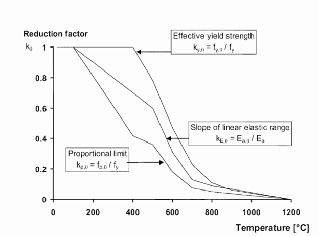
Figure 4: Reduction in yield stress and modulus of elasticity as a function of applied temperature.
SOURCE: Adapted from EN-1993-1-2.
5. Case study: metal chimney under high temperatures
Metal chimneys are subjected to high temperatures from contact with the gases emitted by furnaces. Refractories and insulators are normally used to reduce the temperature acting on the side and maintain the integrity of the equipment. However, there are processes in which the use of refractories is not recommended due to difficulties in maintenance, risk of detachment, contamination of the metal produced, and even accidents. Therefore, some chimneys are built with the inner wall in direct contact with the gas.
In a recent study conducted by Kot Engenharia, a set of metal chimneys compromised by excessive deformation along their entire length was analyzed. Thus, in order to assess the causes of the failures and propose solutions, the work was divided into four stages:
-
- Field inspection to detect non-conformities and design changes;
-
- Temperature measurement with thermographic camera;
-
- Análise estrutural por elementos finitos (estática, flambagem, fadiga, não linear {fluência}) e proposição de soluções;
-
- Monitoring temperatures in newer chimneys to correlate with existing sensors and determine safe operating limits.
5.1. Inspection
During the inspection, deformations were observed throughout the base of the side. To contain the advance of the deformations, a secondary support tower had already been installed to bypass the compressive loading in the area. Figure 5 shows the deformed structure and the shoring tower installed.
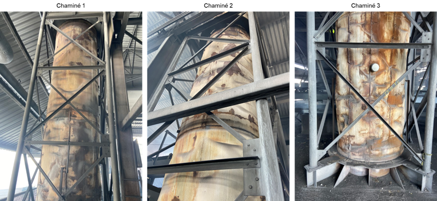
Figure 5: Deformation in the side wall of chimneys with external support structure installed for redundancy and to reduce the risk of structural collapse.
In addition to the deformations, design changes were observed that increased the locking of the chimney, see Figure 6. As illustrated in Figure 1, structures subjected to temperature and with greater restraints are more stressed and generally exhibit higher stresses. For this reason, these design changes were considered in the computational model to assess the causes of equipment failure. Other non-conformities were identified, and solutions were proposed to ensure the integrity of the asset.
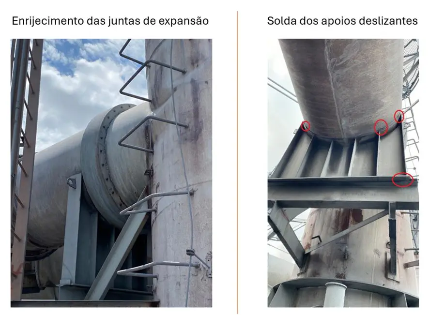
Figure 6: Changes to the expansion joints and sliding supports identified during the field visit.
5.2. Thermographic measurement to define the thermal profile
Thermography is an imaging technique used to obtain the temperature profile of a radiating body. The camera uses sensors to detect and map the infrared radiation emitted by objects or surfaces. Image conversion takes place by calibrating the emissivity parameters of the material, which are defined by the state of the surface and vary as a function of temperature. Therefore, based on the measurements taken, the emissivities of the material were calibrated in order to build the thermal profile of the chimneys.
As a result, after taking measurements and based on the gas temperature records obtained by the company's thermocouples, it was observed that the three chimneys had different temperatures, which varied throughout the day. Therefore, several combinations of temperature distribution between the chimneys were evaluated, following the trend recorded over several days of operation.
Figure 7 shows one of the thermographic images captured, while Figure 8 shows the temperature distribution between the chimneys. In addition to the temperature loads, other actions were considered to determine the load combinations evaluated.
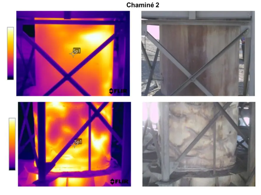
Figure 7: Thermography carried out to determine the temperature profile.
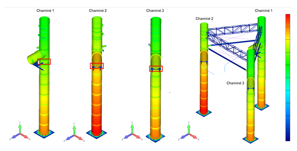
Figure 8: Temperature distribution in the chimneys for one of the loading cases evaluated.
5.3. Structural analysis using finite elements
To characterize the failures and propose reinforcements, several hypothesis tests were performed and different analyses were carried out. Static evaluations indicated failures in some areas of the equipment due to temperature differences, which resulted in distinct deformations from thermal expansion, increasing the acting stresses. In addition, areas susceptible to cracking were identified, as shown in Figure 9. Vale that the most critical areas identified in the study did indeed show damage in the field.
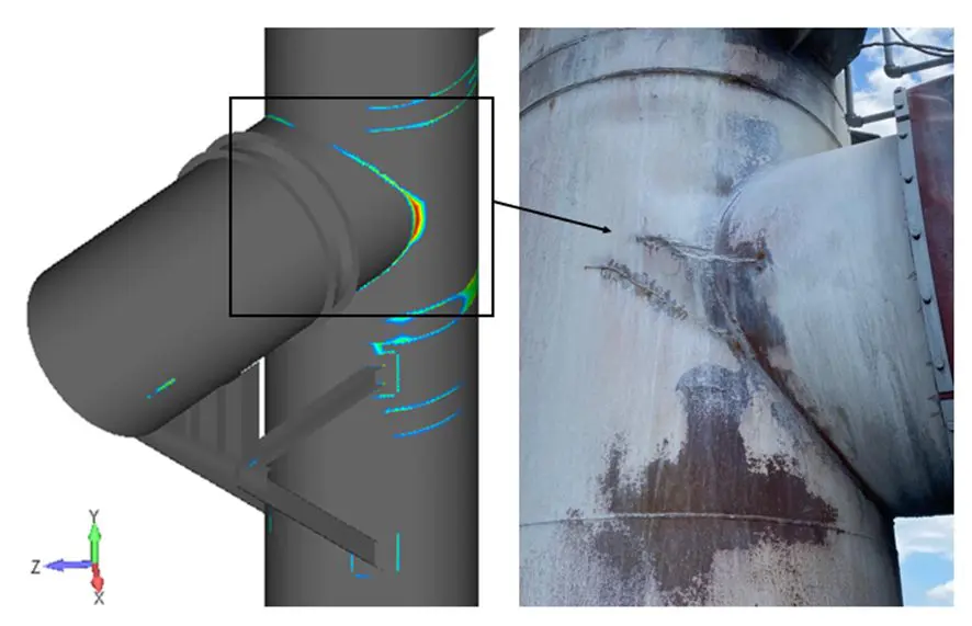
Figure 9: Results of the fatigue analysis, indicating that the useful life of the welds is less than the asset's operating time - highlighting the cracks in the region observed in the field.
Linear buckling analyses and non-linear creep analyses were carried out to characterize the central problem, which was the permanent deformation of the side, since the chimney reached temperatures above 450°C and could reach values close to 620°C, which are critical for the effects of creep deformation.
As a result, the analyses performed identified that the sidewall was at risk of buckling when operating above certain temperatures, as shown in Figure 11. In addition, the nonlinear creep analysis showed that operating the chimney at high temperatures for more than two hours resulted in permanent plastic deformations exceeding the permissible limits, as shown in Figure 10.
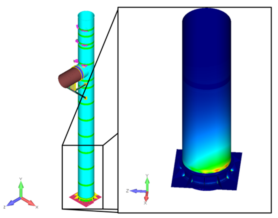
Figure 10: Results of the non-linear creep analysis.
Figure 11: Buckling analysis identifying the risk of buckling on the chimney side.
5.4. Proposed interventions and structural reinforcements
After identifying the problems that caused the structure to fail, the process of proposing reinforcements and improvements began. This stage included some particularities of the process that had to be met, such as: allowing operation up to a certain temperature, not using refractories to facilitate maintenance, reducing the risk of contamination of the material produced and carrying out an assessment to obtain the solution with the least possible economic impact and ease of installation.
As a result, changes were proposed to the material, geometry, improved welds and altered connections to allow the structure to expand. With the proposed reinforcements, it was possible to increase the fatigue life of the most critical welds by 350%, adapt the structure to the buckling resistance requirements for the entire operating temperature range and allow the new chimney to operate at temperatures of 600°C for periods of up to 10 hours, improving process control and guaranteeing the safety and operational integrity of the structure. The following figures exemplify the proposed modifications (Figure 12) and the results of the analysis considering the implementation of the reinforcements (Figure 13).
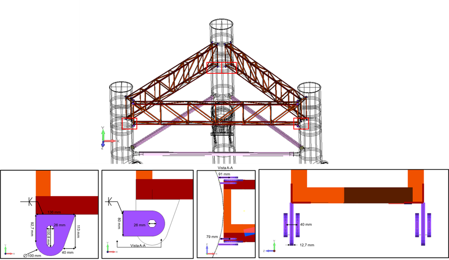
Figure 12: Example of a proposed modification to improve the structure's thermal expansion.
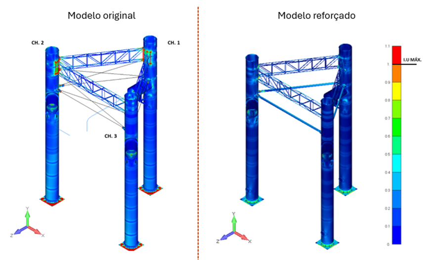
Figure 13: Comparative results of the static analysis before and after implementation of the reinforcements.
5.5. Continuous monitoring with thermocouples for the development of operational controls
As the material's resistance is dependent on the operating temperature, it was necessary to establish safe operating limits, as the materials have physical resistance limits (see Figure 4). Continuous monitoring was therefore carried out using thermocouples welded to the side structure, in order to determine a correlation between the gas measurement sensor and the side temperature. This correspondence has allowed the client to work under safe operating conditions at all times.
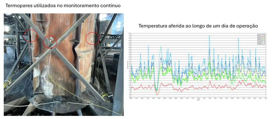
Figure 14: Continuous temperature instrumentation in the chimney for process control.
6. Conclusions and lessons learned
After the detailed study carried out by Kot, it was observed that the chimney failures were related to changes in the support conditions of the ducts and, above all, to the high operating temperatures. The results of the buckling and non-linear creep analyses assertively represented the state of deformation verified in the field, indicating that the models built are faithful to reality.
Thus, with the proposed modifications to the geometry and the indication of safe operating ranges, it was possible to design a structure suitable for operation and within the installation and cost constraints specified by the client. In conclusion, this work highlights the importance of understanding the physical phenomena involved and the accuracy achieved with the correct use of the finite element method, both in characterizing failure aspects and in proposing simpler and more efficient reinforcements and adjustments.
7. Finite element analysis is with Kot Engenharia
If you, like our more than 150 clients, are looking for specialized solutions in structural analysis or failure prevention such as deformation, vibration, and corrosion, consult our team and count on Kot Engenharia.
Since 1993, we have been offering engineering consulting services through technical studies using non-destructive testing, field instrumentation, and computational simulations (FEM, DEM, and CFD) for highly complex diagnostics in concrete and metal structures and industrial equipment.
Follow our pages on LinkedIn, Facebook and Instagram to continue following our content.
FAQ
1. What is the phenomenon of creep, and why is it so critical for chimneys without refractory lining?
Creep is the slow, progressive, and permanent deformation that occurs in a metallic material when subjected to a constant stress at high temperatures (generally between 30% and 60% of the metal’s melting point). In the case studied, since the chimney operated without an internal refractory lining (to prevent contamination of the production process), the steel wall was in direct contact with the gases and reached peak temperatures of up to 620°C. Under this intense heat, the steel loses rigidity and begins to deform plastically under the effect of its own weight and geometric constraints, resulting in irreversible deformations and a serious risk of collapse due to buckling.
2. How did the jamming of the expansion joints accelerate the failure of the sidewall?
When metal is heated, it undergoes thermal expansion and needs space to expand. If the structure has sliding supports and free joints, it increases in size without accumulating large internal stresses. However, the field inspection detected design changes that blocked the movement of these joints. With expansion restricted, the expansion energy was converted into massive internal compressive stresses in the side walls. The metal, prevented from expanding upward, relieved the stress by deforming laterally, while also concentrating severe stresses that caused premature cracks in the welds due to thermal fatigue.
3. What is the difference between weak and strong thermo-structural couplings in finite element modeling (FEM)?
The difference lies in the interdependence of the simulated physical phenomena:
-
Weak coupling: The thermal analysis is first solved in isolation to determine the structure’s temperature field. The data generated is then exported and applied as a load to the structural model. The structure’s deformation does not alter its thermal properties. This is the most common method due to its lower computational cost.
-
Strong coupling: The thermal and structural equations are solved concurrently (at the same time) at each calculation step, such that a change in one parameter instantly affects the other.
4. How was infrared thermography used and calibrated to map the thermal profile of the chimneys?
Thermography detects the infrared radiation emitted by the chimney’s surface. However, for the image to show the exact actual temperature, engineers need to calibrate the material’s emissivity (the surface’s ability to emit thermal energy). This calibration was performed by correlating the infrared camera images with historical gas temperature data recorded by the plant’s internal thermocouples. This made it possible to map, with mathematical precision, how heat was distributed along the entire side of the chimney at different times of the day.
5. How did the combination of geometric modifications and thermocouple instrumentation solve the customer's problem in practice?
First, the engineers redesigned the geometry of the supports and connections to allow the structure to expand freely, which increased the service life of the critical welds by 350%. To ensure long-term operational safety, thermocouples were welded directly onto the steel shell. This continuous monitoring established a real-time correlation between the gas temperature and the plate temperature, allowing operations to know exactly when the asset is operating within a safe zone (allowing, for example, peaks of 600°C for up to 10 hours without triggering the creep limit).


