Mechanical behavior of concrete
Since reinforced concrete is a composite material, it has physical properties that differ from the materials that make it up on their own.
Single-piece steel reinforcements are responsible for giving the pieces ductility, with high tensile strength, while the concrete provides compressive strength. When loads are applied to a concrete part, it is common for cracks to appear in the tensile region.
Concrete has what is known as partially brittle behavior, which is characterized by a small region of linearity, followed by softening, which is a non-linear behavior. The interaction of defects inherent in concrete, such as voids and micro-cracks, results in a typical tensile response. The behaviour of concrete is characterized by a linear elastic region followed by a softening region before the maximum stress. After developing the maximum stress, the concrete shows an increase in deformation with a reduction in stress, which characterizes thesoftening region. Materials with this behavior are classified as partiallybrittle (quasi-brittle).

Figure 1 - Typical stress-strain curve for concrete,Eis secantmodulus and Eit tangentmodulus .
Some manifestations of cracks in parts
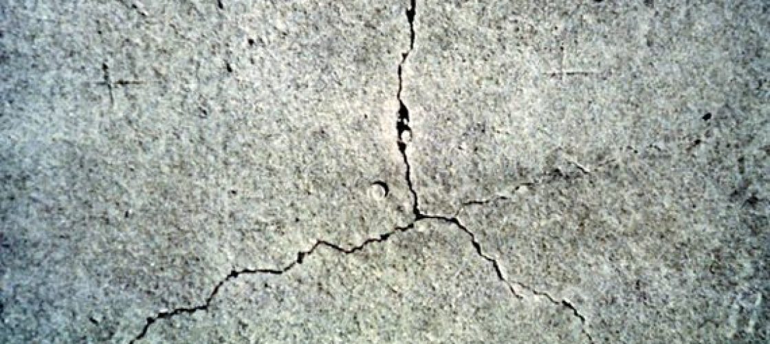
Cracks can originate during the construction of the part itself, as a result of autogenous stresses due to the solidification process of the concrete. If the solidification process is not controlled, cracks can occur. The amount of water required by the concrete during the solidification process is essential to avoid rapid hardening, which results in excessive cracking.

Figure 2 - Example of a crack developed due to shrinkage in the process of
hardening concrete - Source: PCA - Portland Cement Association.
Excessive cracking exposes the reinforcement to moisture and can lead to various pathological manifestations in reinforced concrete. The most common is corrosion of the reinforcement, whose expansive reactions cause the concrete to spall.
Another manifestation is the alkali-aggregate reaction, which is potentiated or even triggered by the presence of excessive moisture inside the concrete.

Figure 3 - Example of pathological manifestation - alkali-aggregate reaction
- Source: PCA - Portland Cement Association.
Fracture mechanics of concrete
The study of crack propagation in reinforced concrete parts can be carried out using fracture mechanics, but with some peculiarities. The use of linear models (MFEL - linear elastic fracture mechanics) is not very suitable for reinforced concrete parts due to the behavior of the material.
Crack propagation mechanisms in reinforced concrete parts are non-linear, mainly due to the existence of a cementitious matrix, fine aggregate and coarse aggregate, where each of these phases has different fracture toughness properties.

Figure 4 - Example of crack propagation in concrete, (a) high toughness of the aggregate in relation to the cementitious matrix, (b) aggregate with slightly higher toughness than the matrix, Chen, Y. P., 2006.
For numerical analyses, appropriate propagation models must be applied in order to reproduce the elasto-plastic behavior of the fracture process zone (FPZ), which forms in the vicinity of the crack. Another aspect that adds non-linearity to crack propagation behavior are the toughness mechanisms that form during the propagation process, called crack arresting mechanisms.

Figure 5 - Regions developed near a crack, (L) linear region, (F) in the process of fracture, (N) non-linear, Bazant and Oh (1983).
Study model
In a typical fracture mechanics analysis model, a crack is initially added and propagated at each step of the analysis. In this calculation procedure, the stresses in the part are modified due to the presence of the crack, which changes the direction of crack propagation at each analysis step.

Figure 6 - Simulation of crack propagation (embedded crack) in a concrete part - using an initial crack, the model reproduces the propagation path based on the stress field.
During a propagation simulation, it is possible for the crack to stabilize, resulting in a crack that propagates and remains stable after a certain length.
One of the most widely used models for representing non-linearity at the crack tip is the cohesive crack model. This model consists of adding stresses at the crack tip in order to represent the fracture process region (ZPF - zona de processo de fractura). This region is characterized by the accumulation of micro-cracks and interlocking of the aggregate, and is considerably larger when compared to the plastic zone in a ductile material such as steel. This condition makes it impossible to use linear elastic fracture mechanics (LELM) in concrete elements.
The cohesive zone then corresponds to a micro-fractured region where there are ligaments responsible for transferring stress, while the material located outside the fractured region maintains its strength unchanged.

Figure 7 - Cohesive crack model proposed by Hillerborg.
The technique of concrete fracture mechanics can be applied to study the propagation pattern of cracks in reinforced concrete parts. This approach via numerical analysis models is particularly important for determining the crack pattern and its causes, making it possible to reproduce the same crack pattern observed in the field.
This technique can also be applied in cases where the remaining life of reinforced concrete parts with significant cracks is to be determined. The example below shows a transverse beam of a viaduct with cracks, where fracture mechanics is a tool for determining the severity of the crack, the reduction in the strength of the part and the cause of the damage.

Figure 8 - Example of a major crack in a road viaduct crossbeam
that can be investigated using non-linear fracture mechanics.
Kot Engenharia has the experience and resources necessary to carry out simulations and in-depth studies in concrete fracture mechanics such as those described in this article. Contact our team for more information!
Follow our pages on LinkedIn, Facebook e Instagram to keep up with our content.


